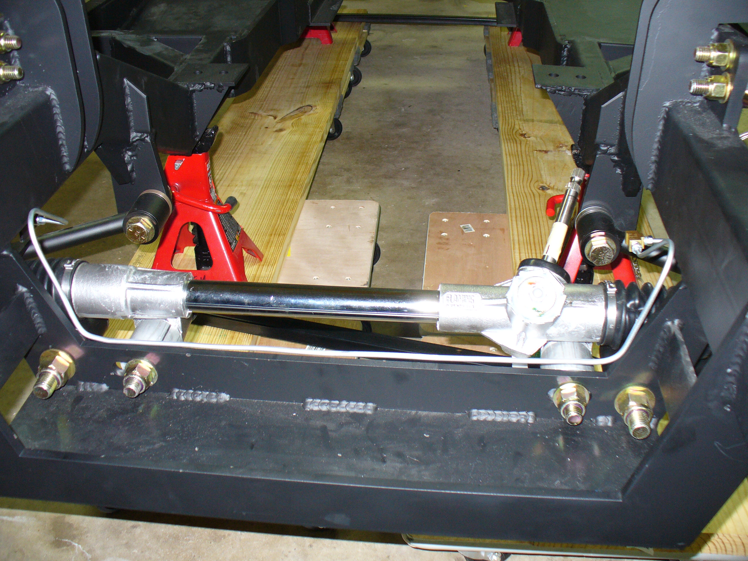
Here is the emergency brake installation. Pretty straightforward…
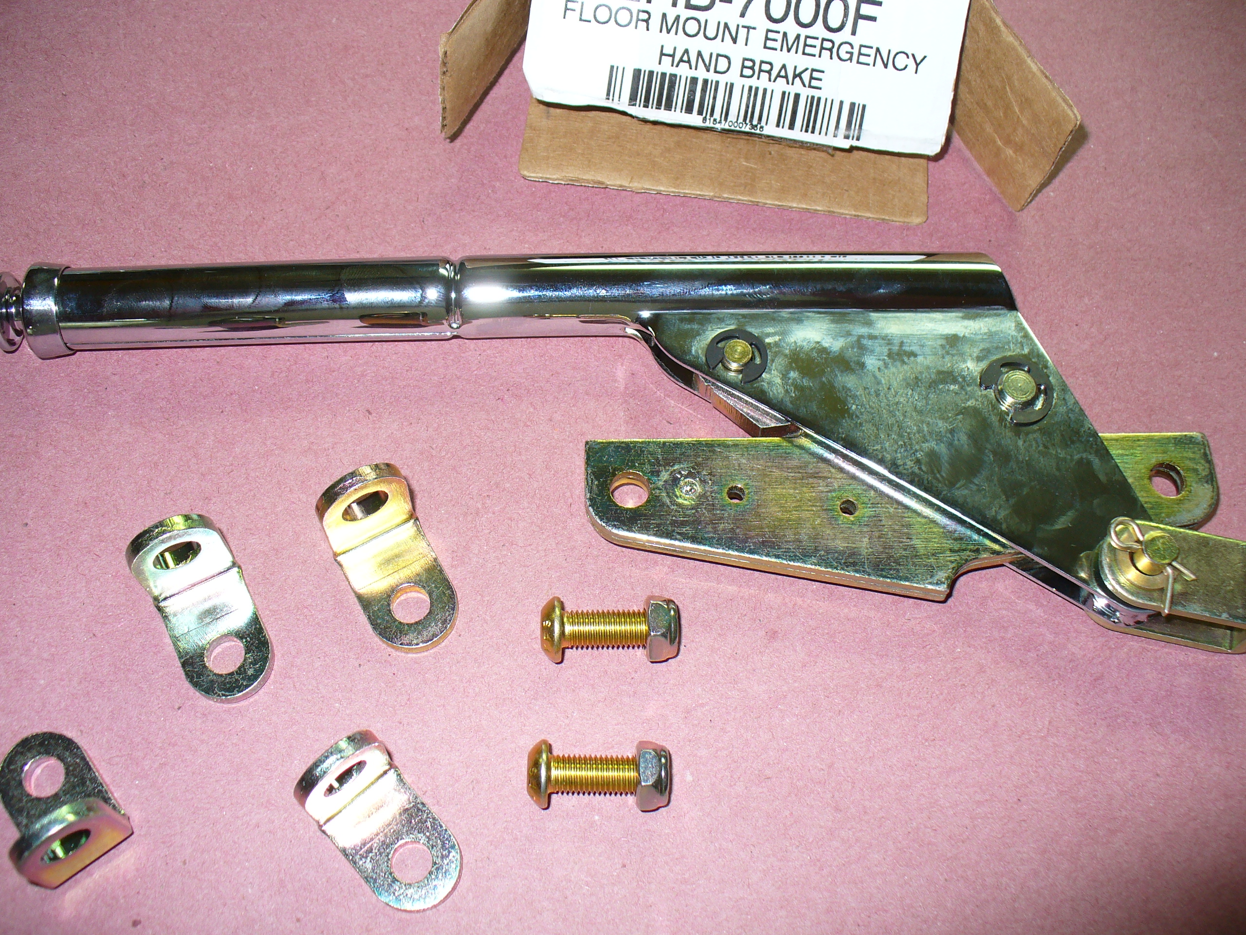


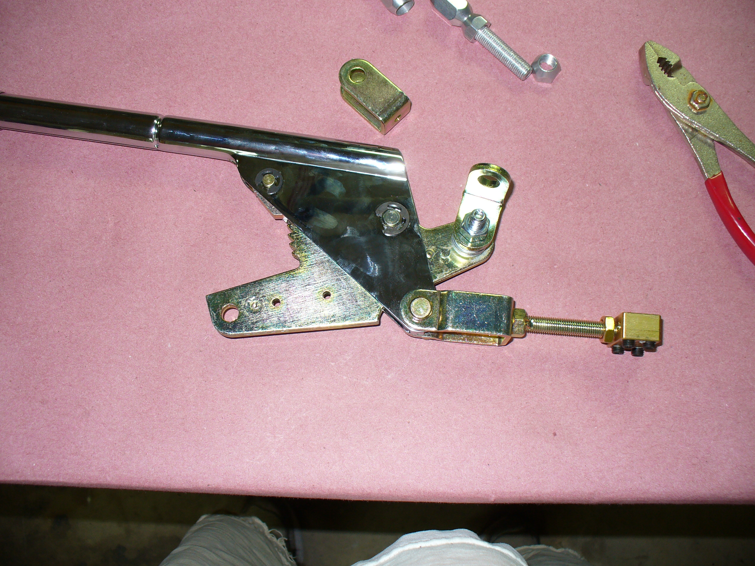


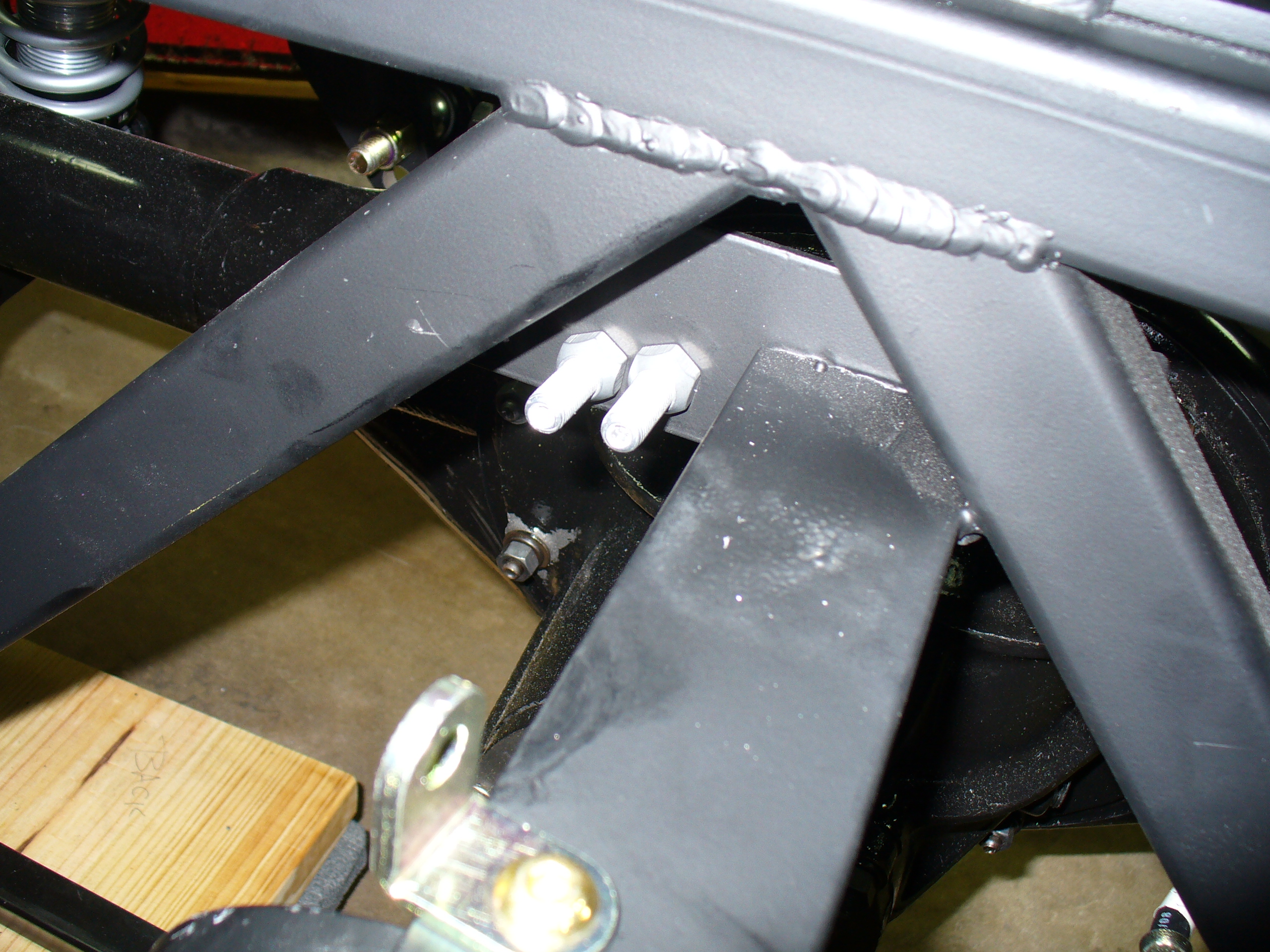


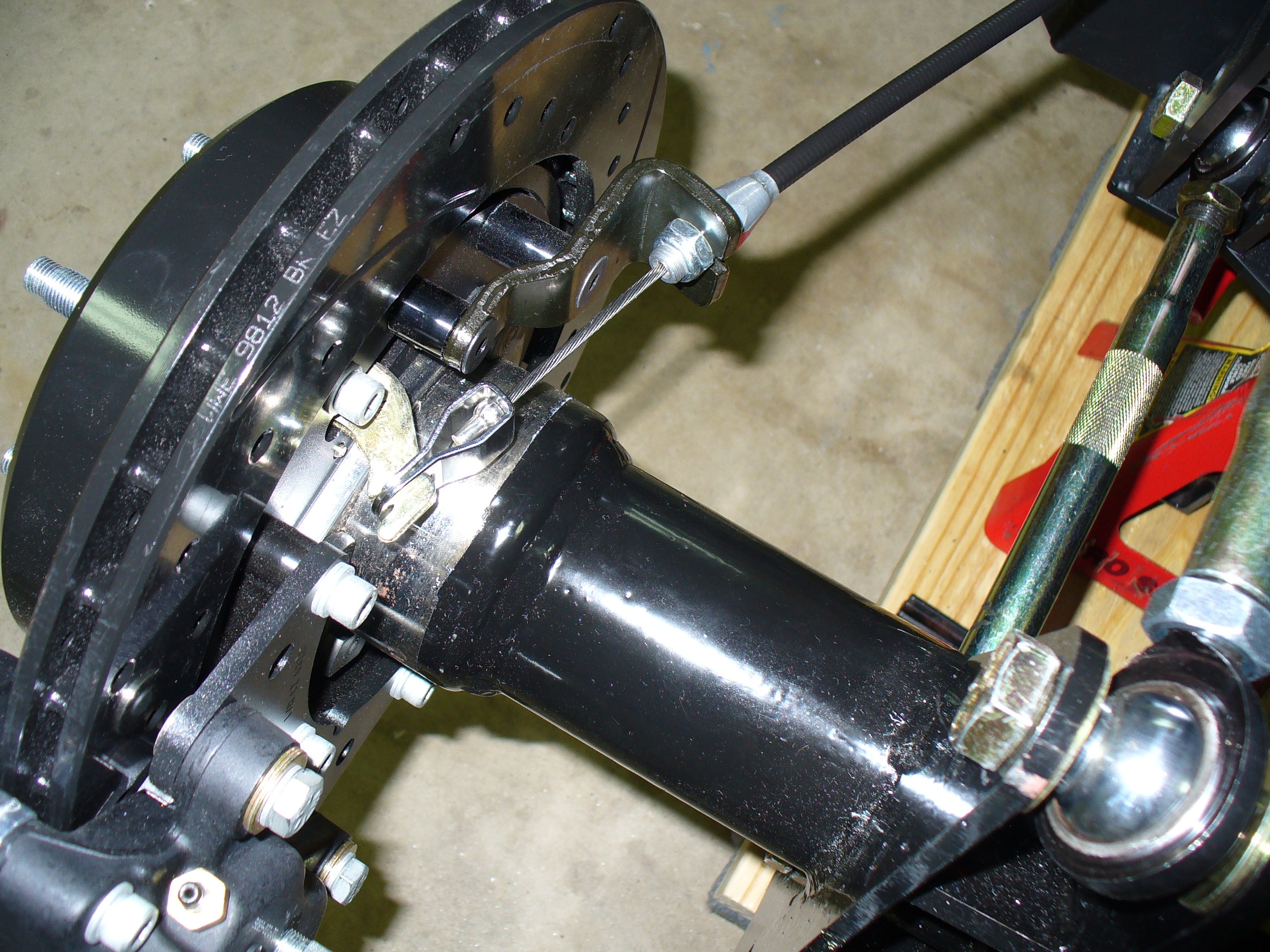


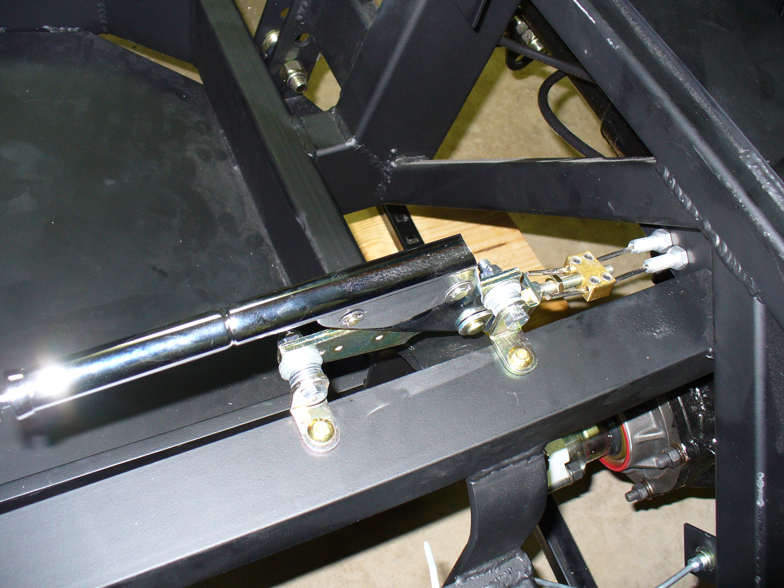
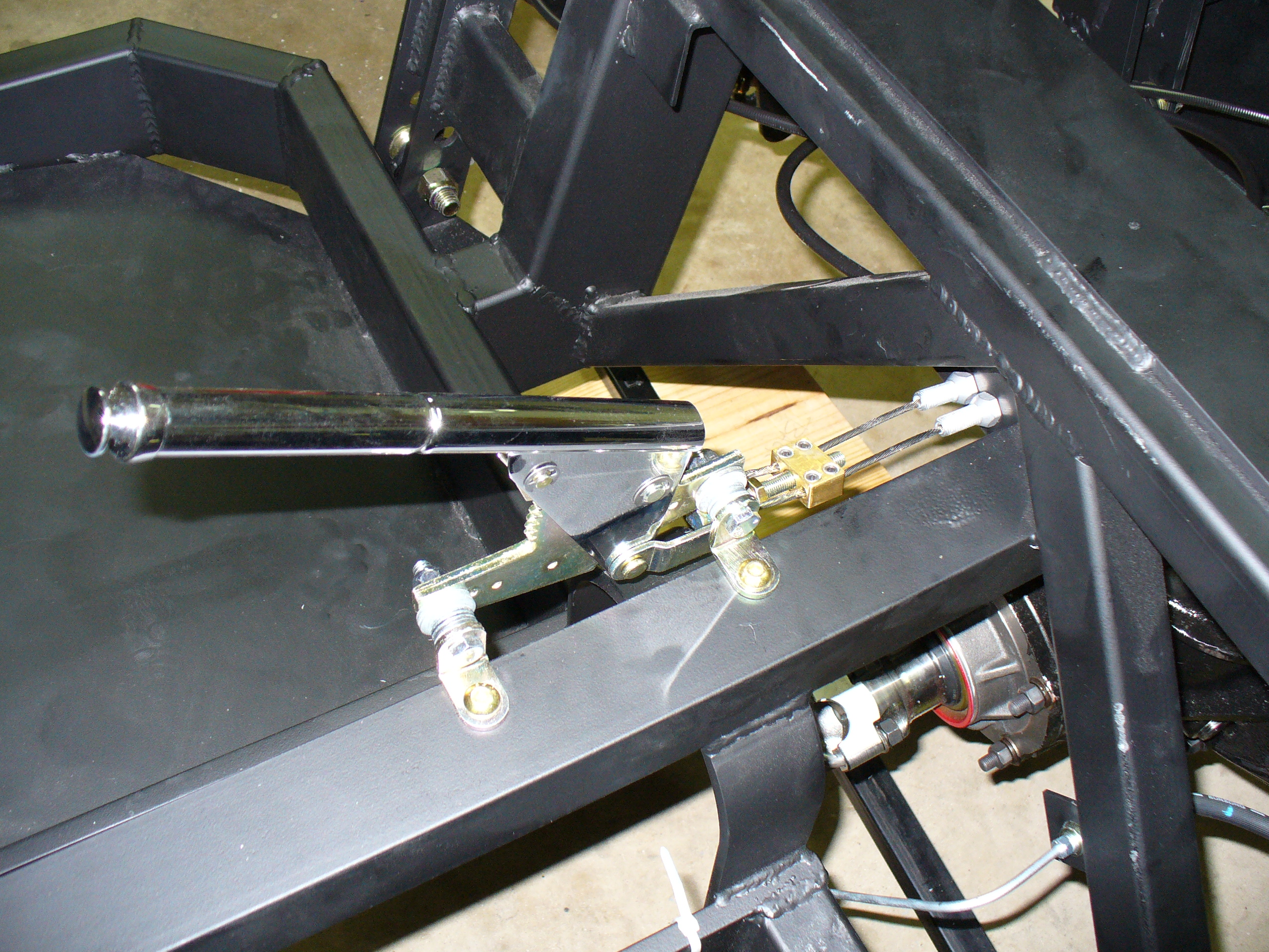
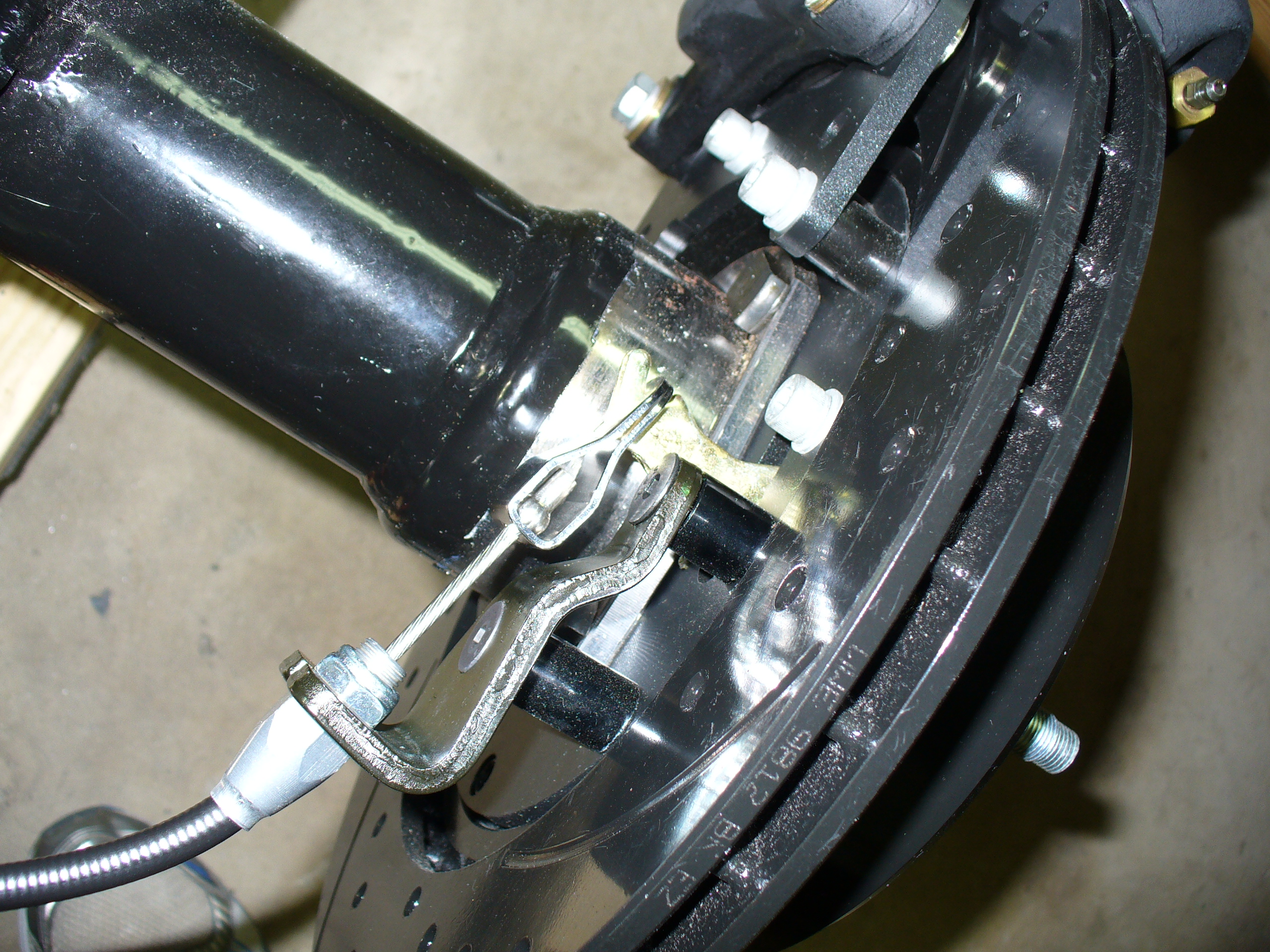

Here is the emergency brake installation. Pretty straightforward…
This is the nice braided fuel line that came with the kit. However, when I removed the tape to attach the fitting, the braiding started to unravel. I had to put on a hose clamp to make it stop.

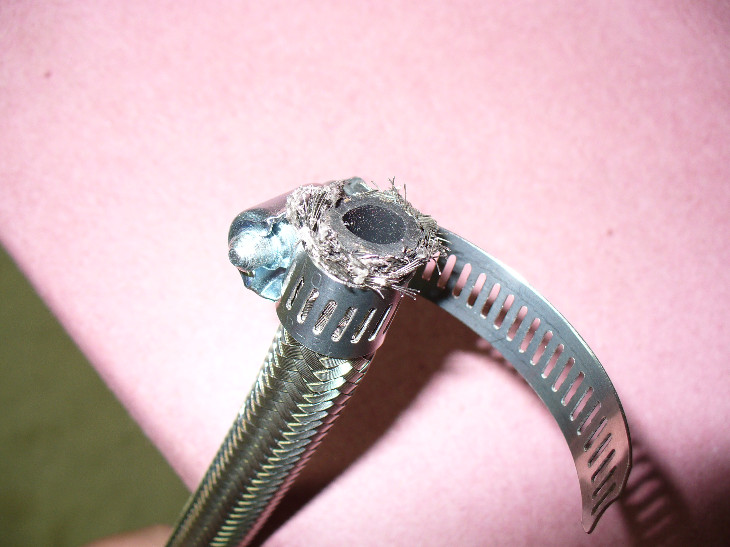
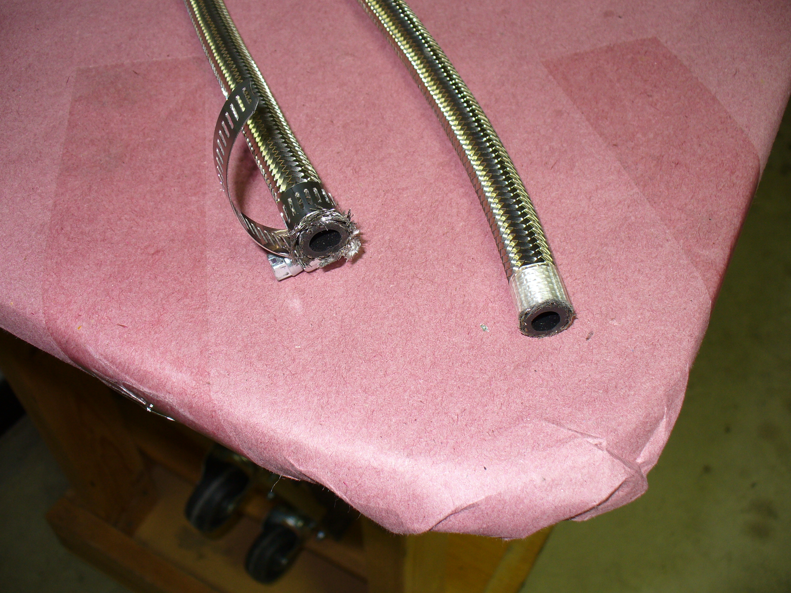
I will need to go to a speed shop or get more information on how to get the AN fittings onto the end of the line. Stay tuned…
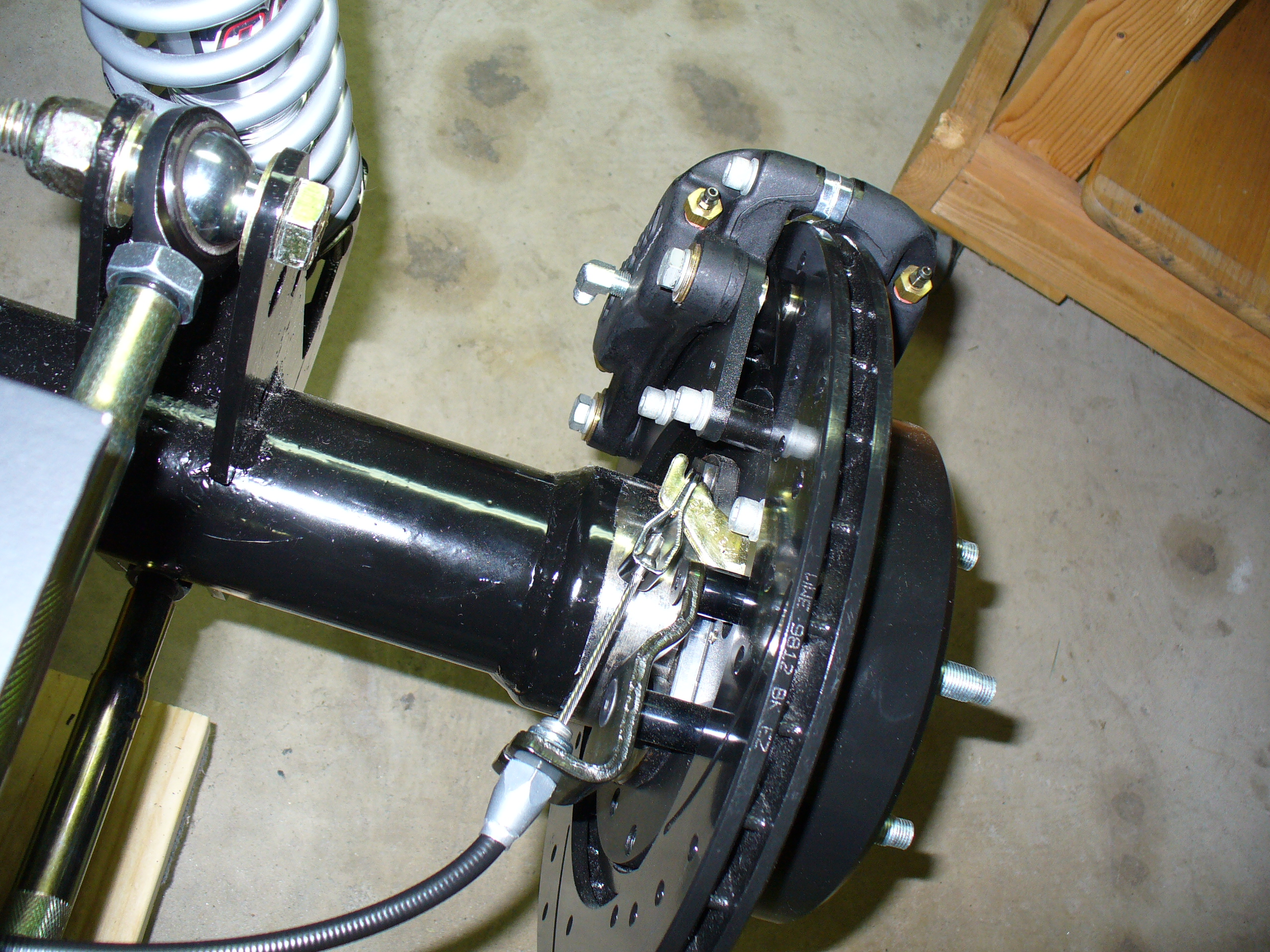
This last weekend I made great progress on installing the brakes.
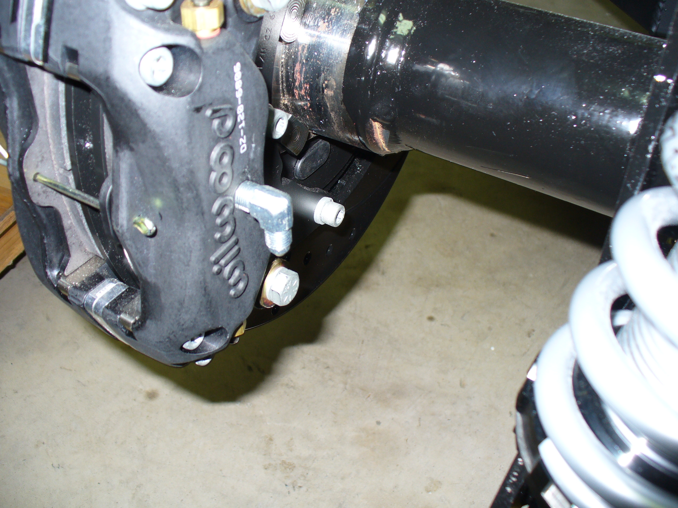
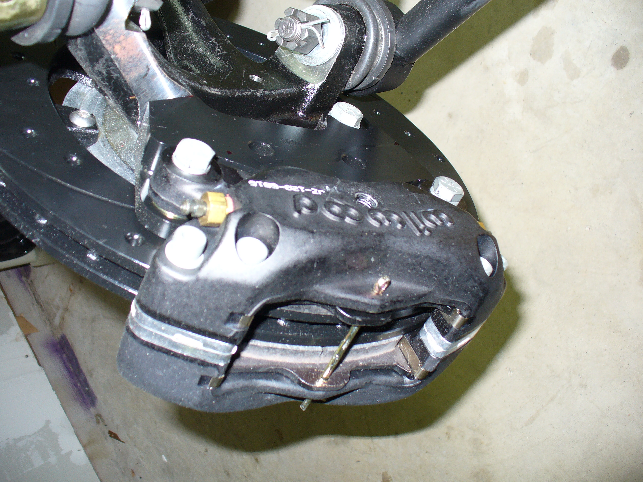
Here is the inside of the caliper: note the hole where the fitting goes.
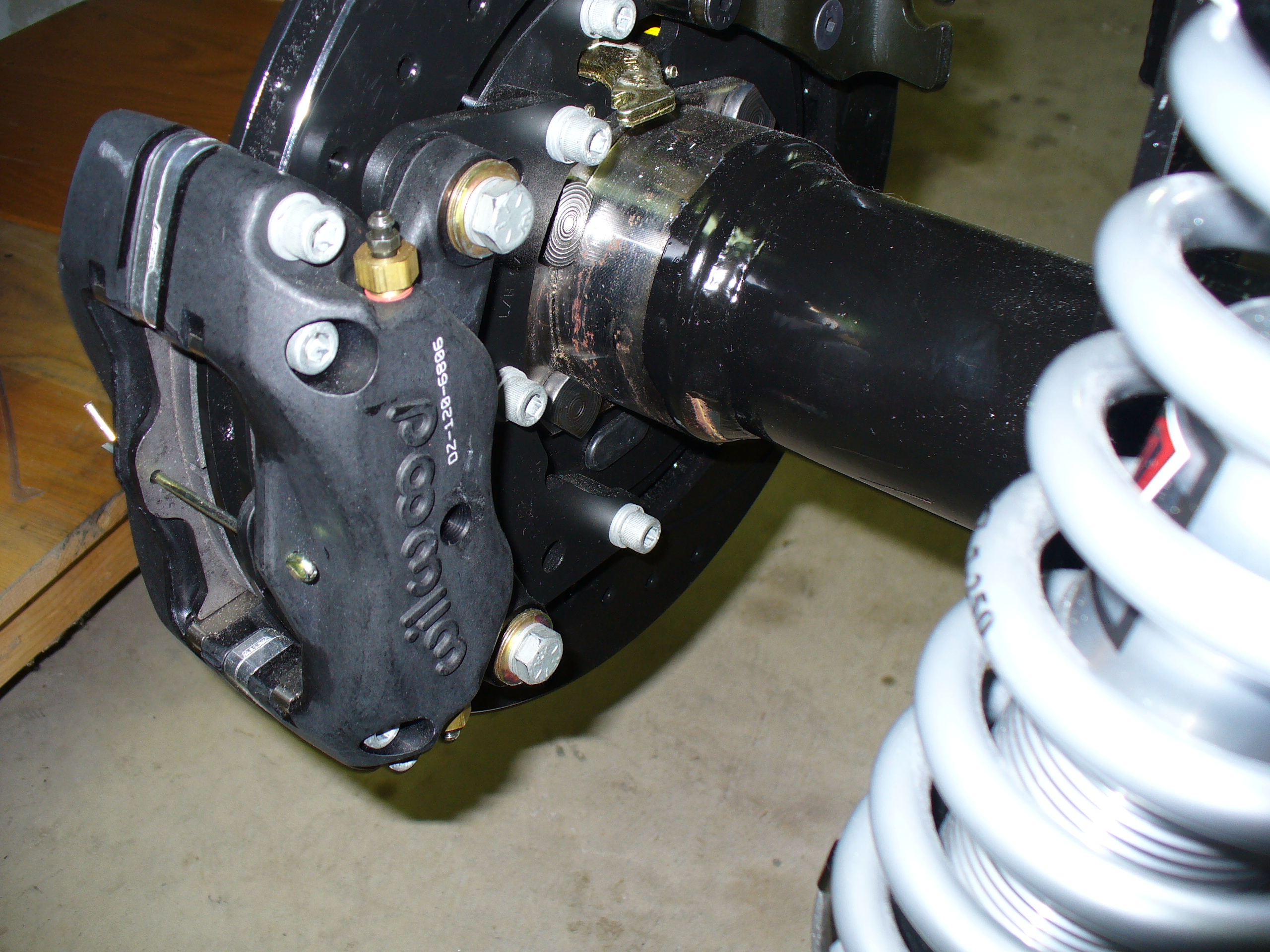
Installed fitting here:
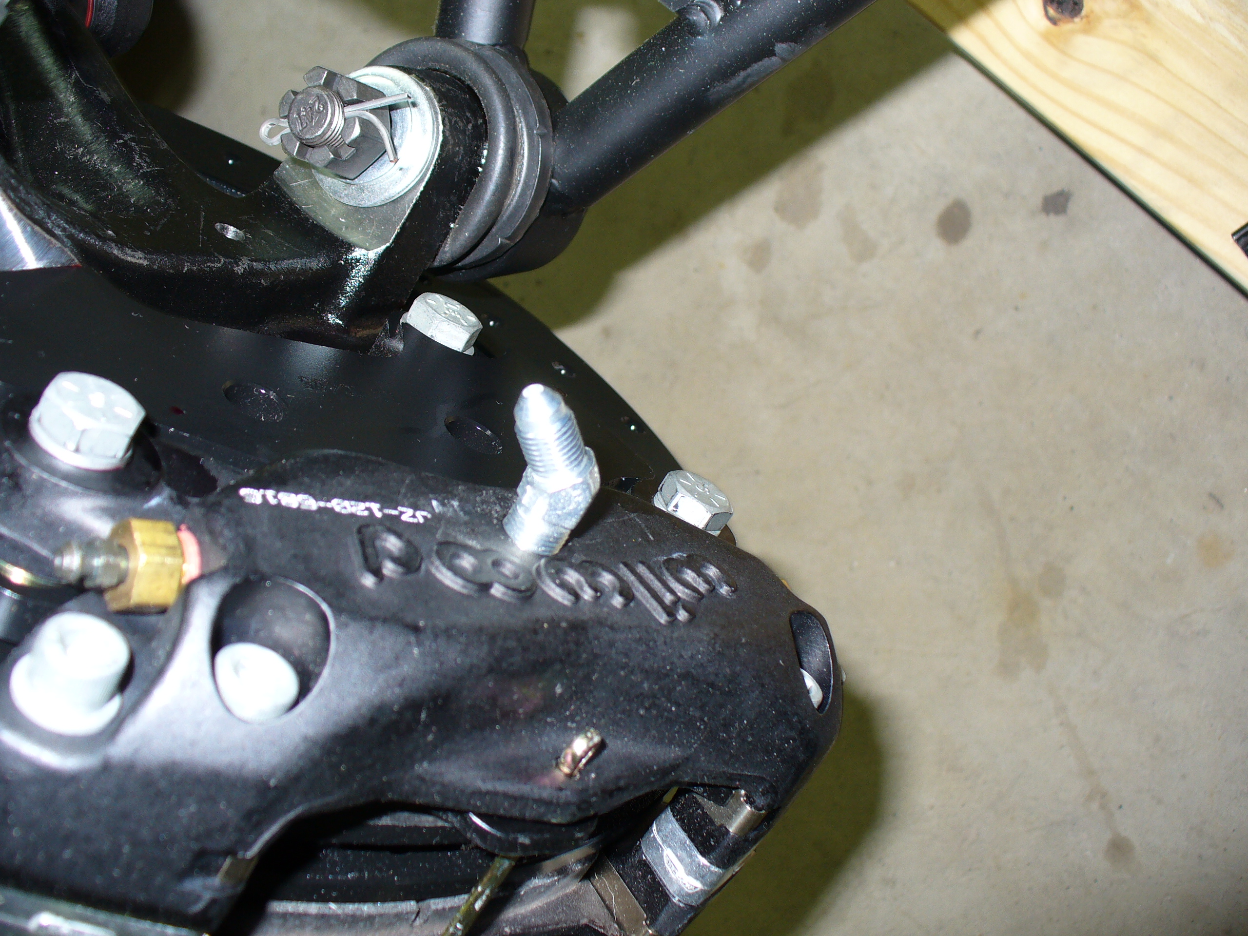
Fitting for front hard bracket:


Flexible line to the front calipers:

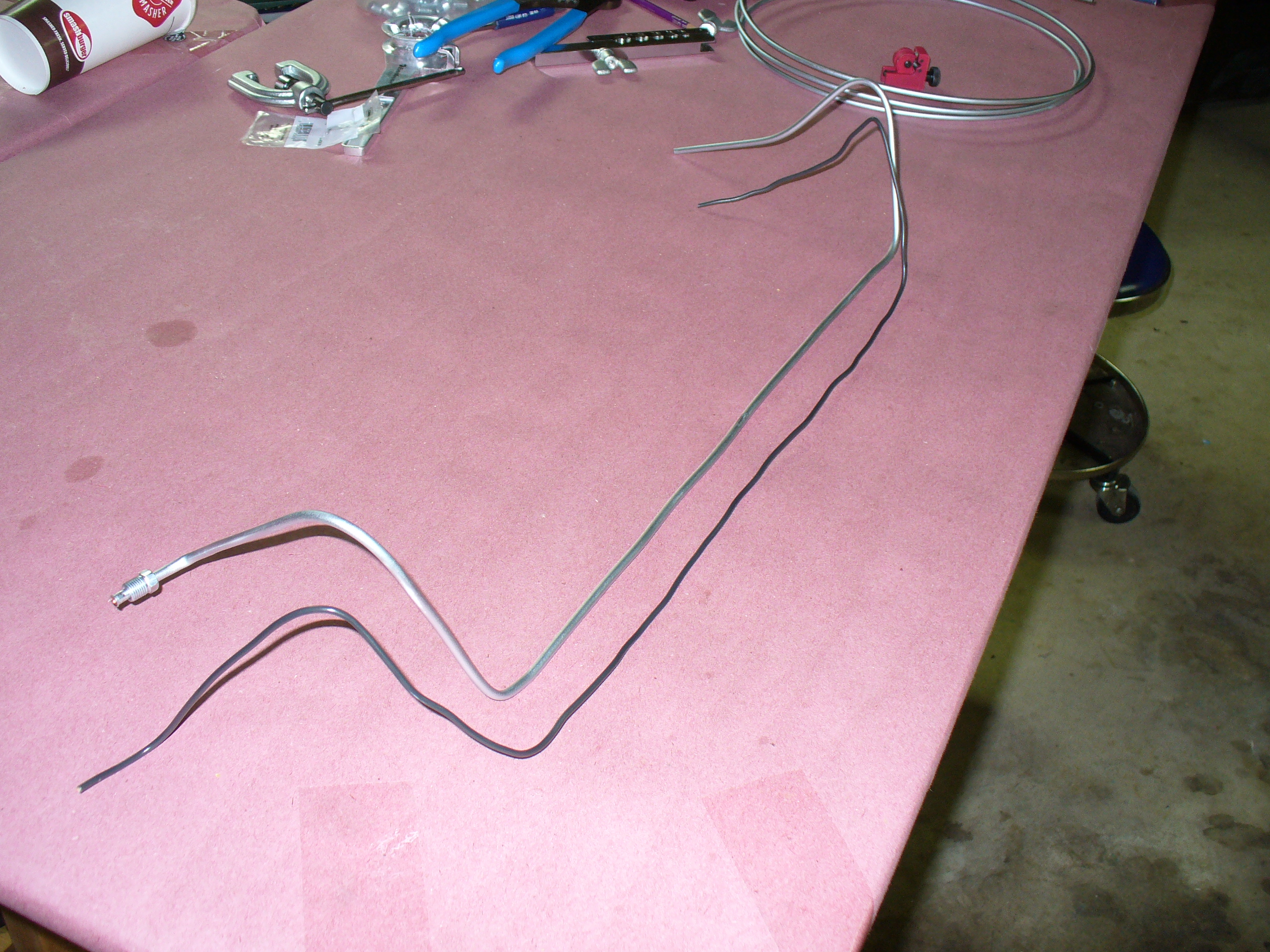
Using an ordinary black electrical wire I made a model of what the front brake line will look like…

…and here is the brake line I will bend into this shape.


Brake line flaring:
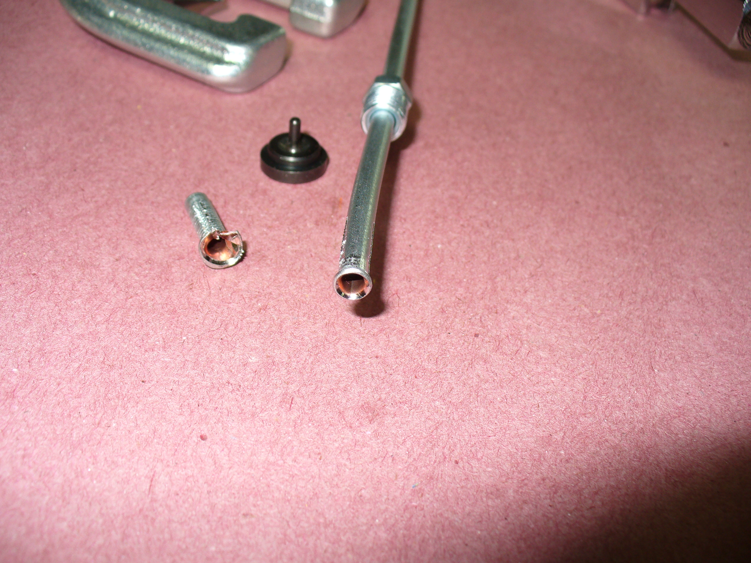
Here is the formed brake line:
Brake line fit into the front of the car:


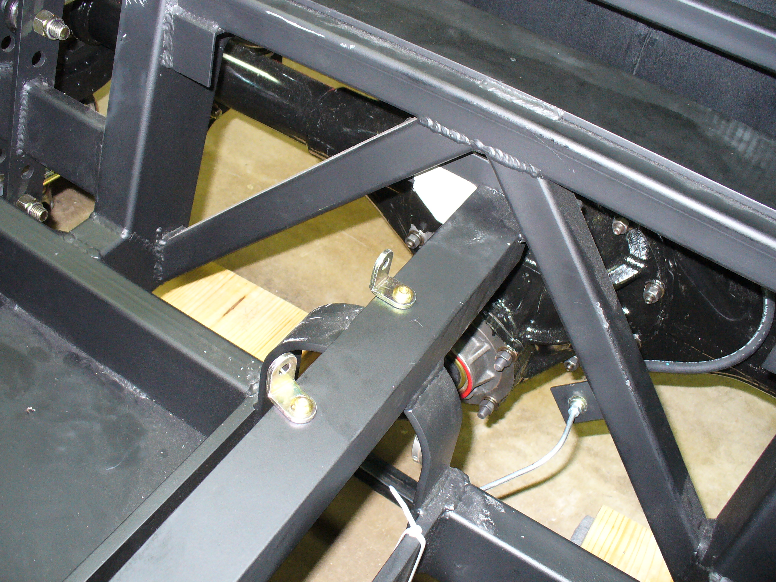
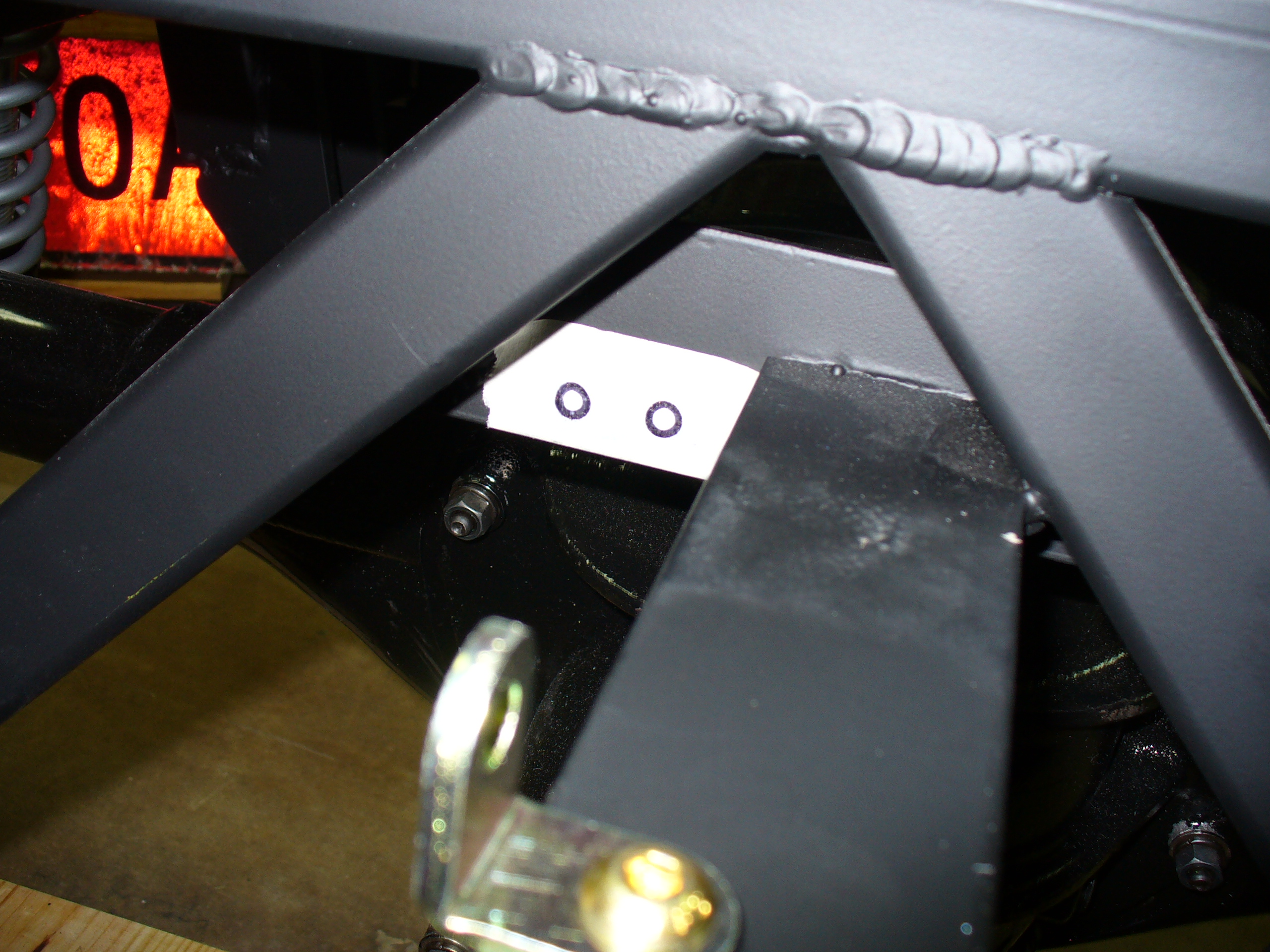
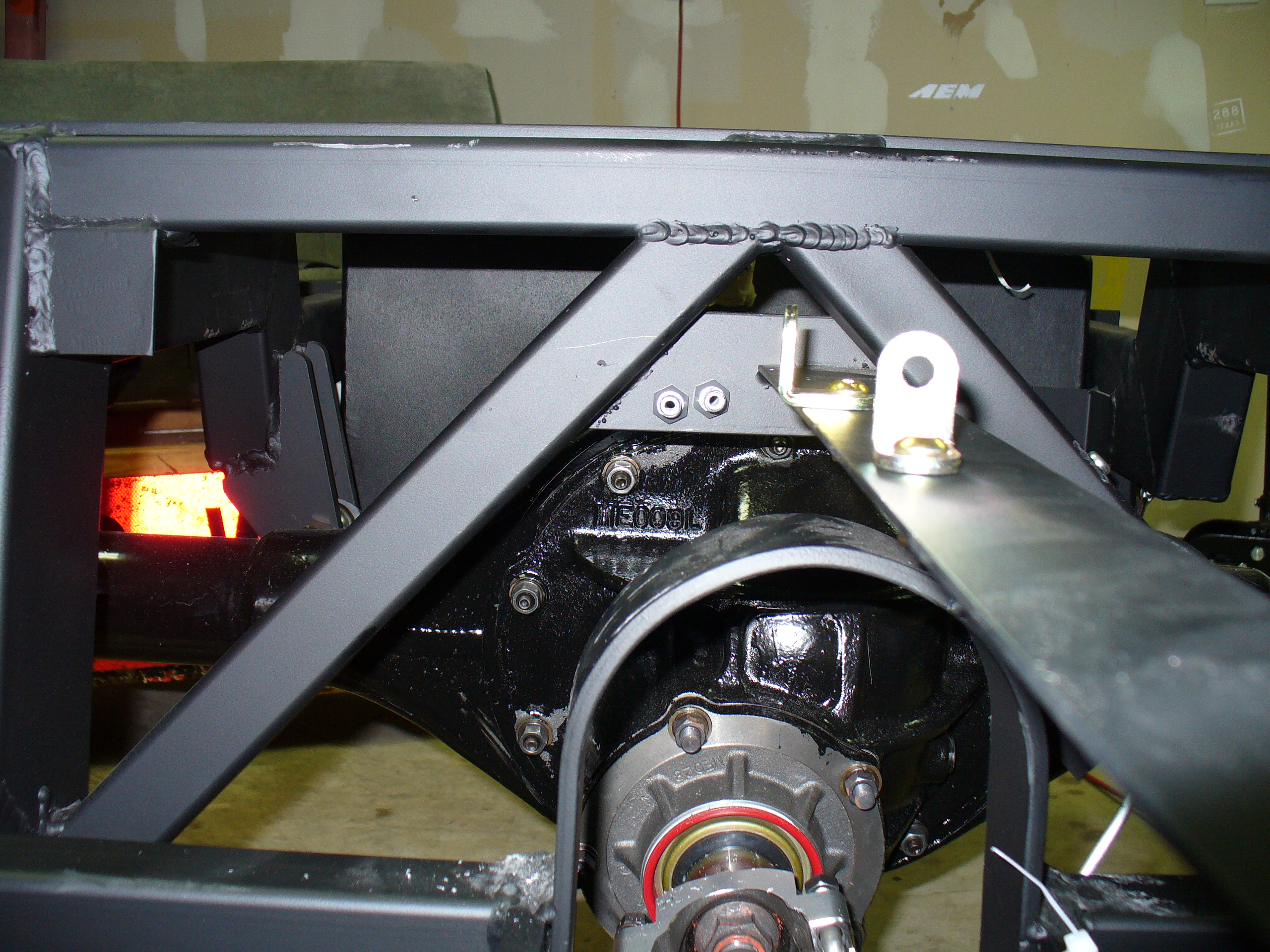
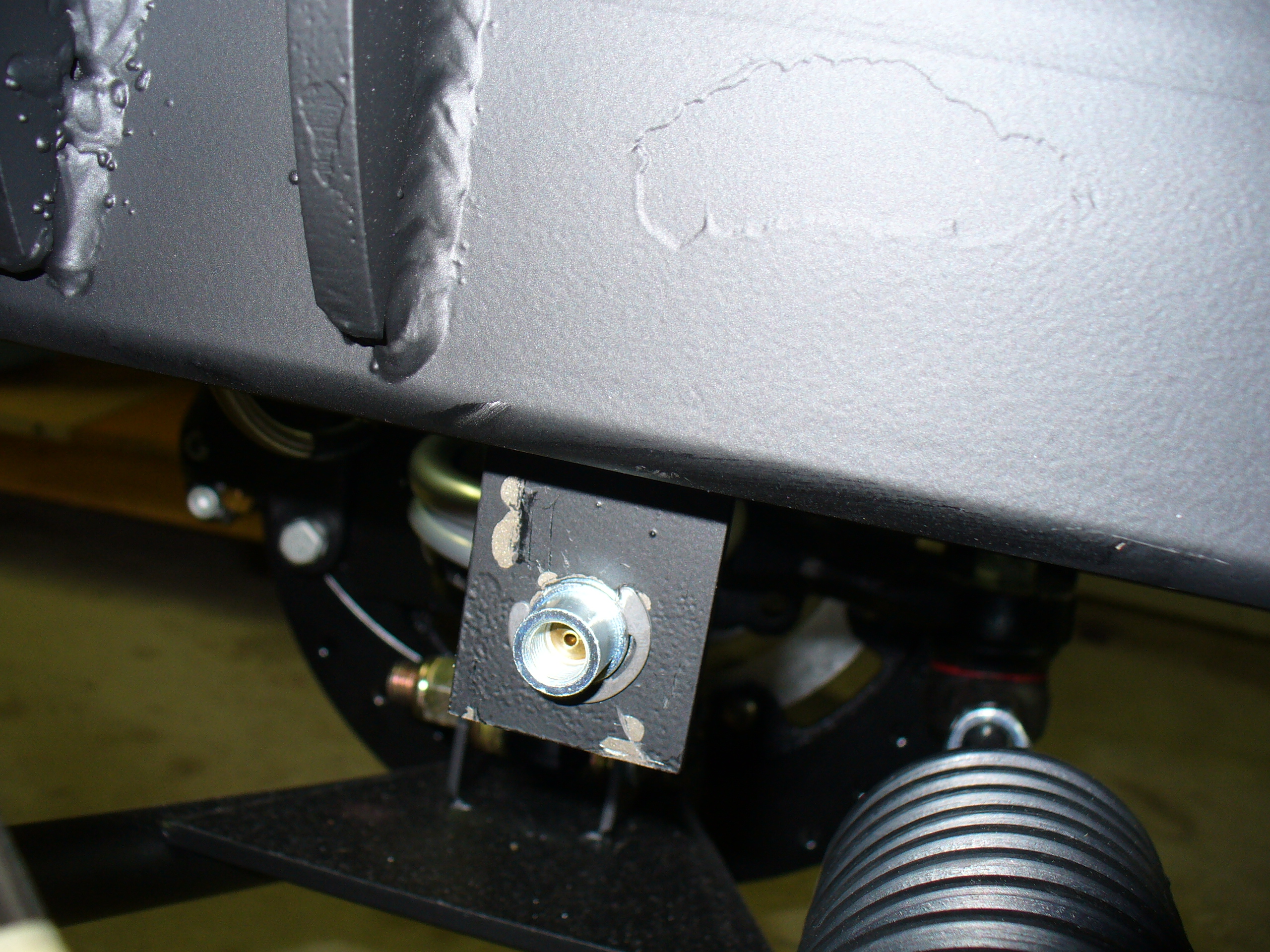
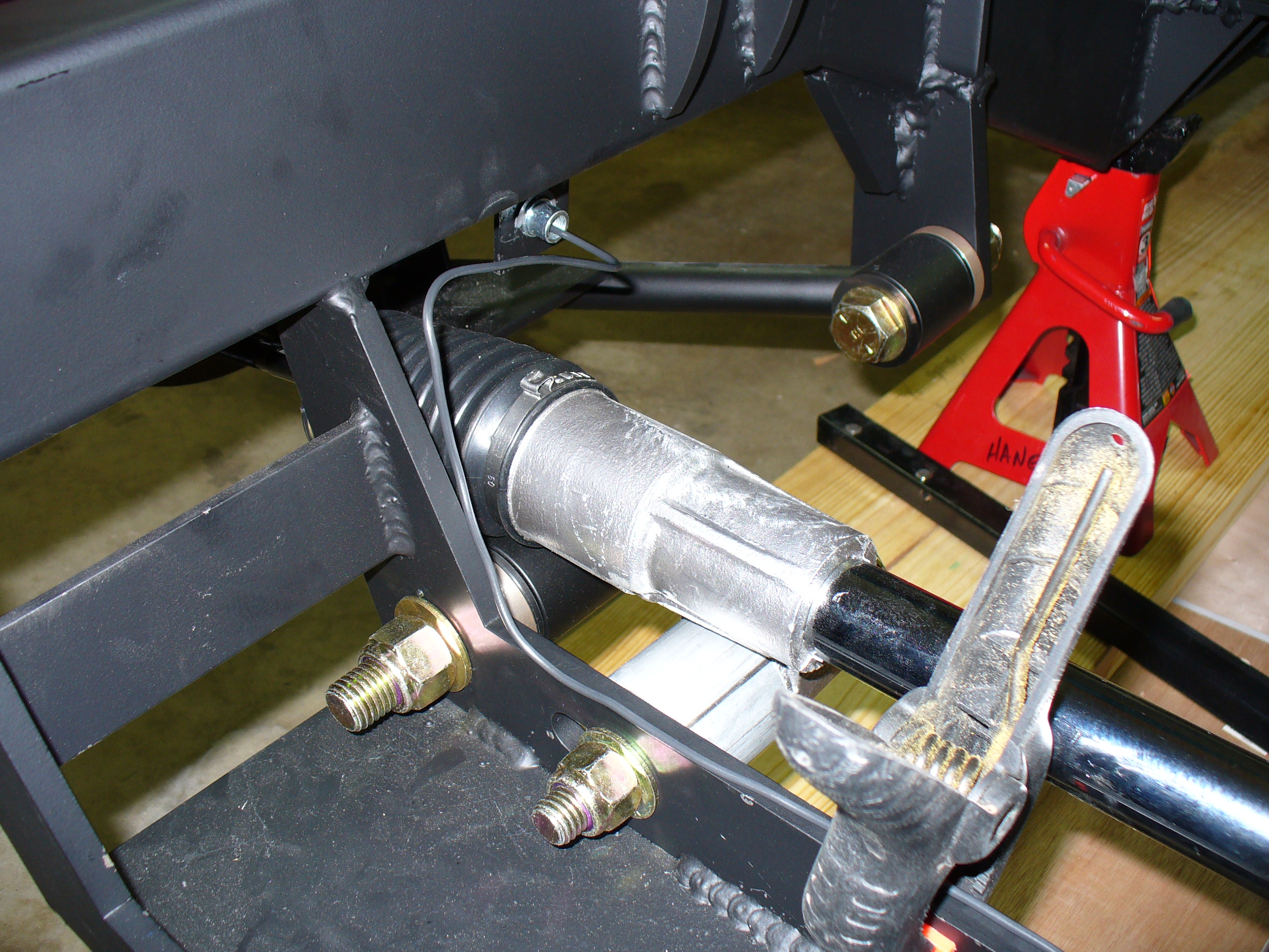
Here is where the flexible brake line attaches to the panhard bar in the rear. First, I marked where the hole can be, avoiding a double layer of steel:


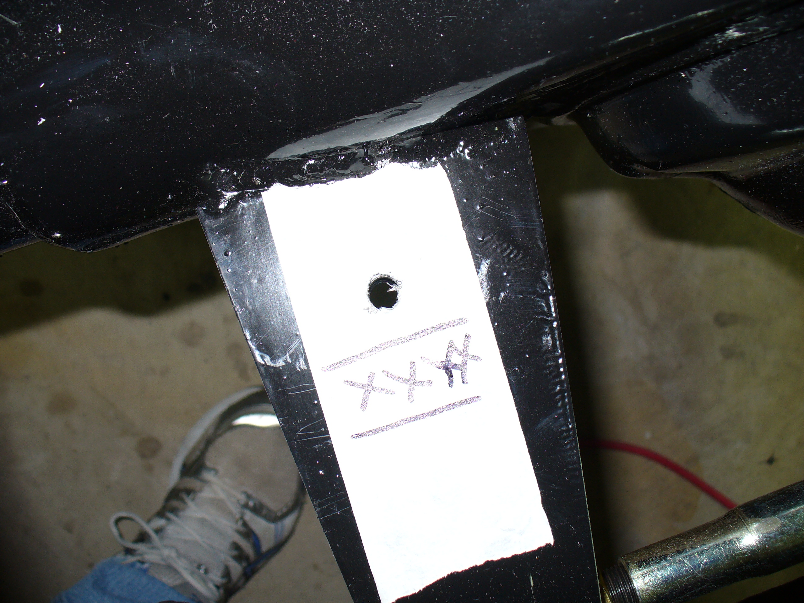
After drilling the hole, it fit in quite well.


The other end of this flexible line fits through another hard bracket on the frame. This connects to another piece of 3/16 inch steel brake line that runs along the inside of the transmission tunnel.


I will replace these zip ties with brackets, once I get the fuel lines ready to run.
Next on the list: installing the brake and fuel lines.
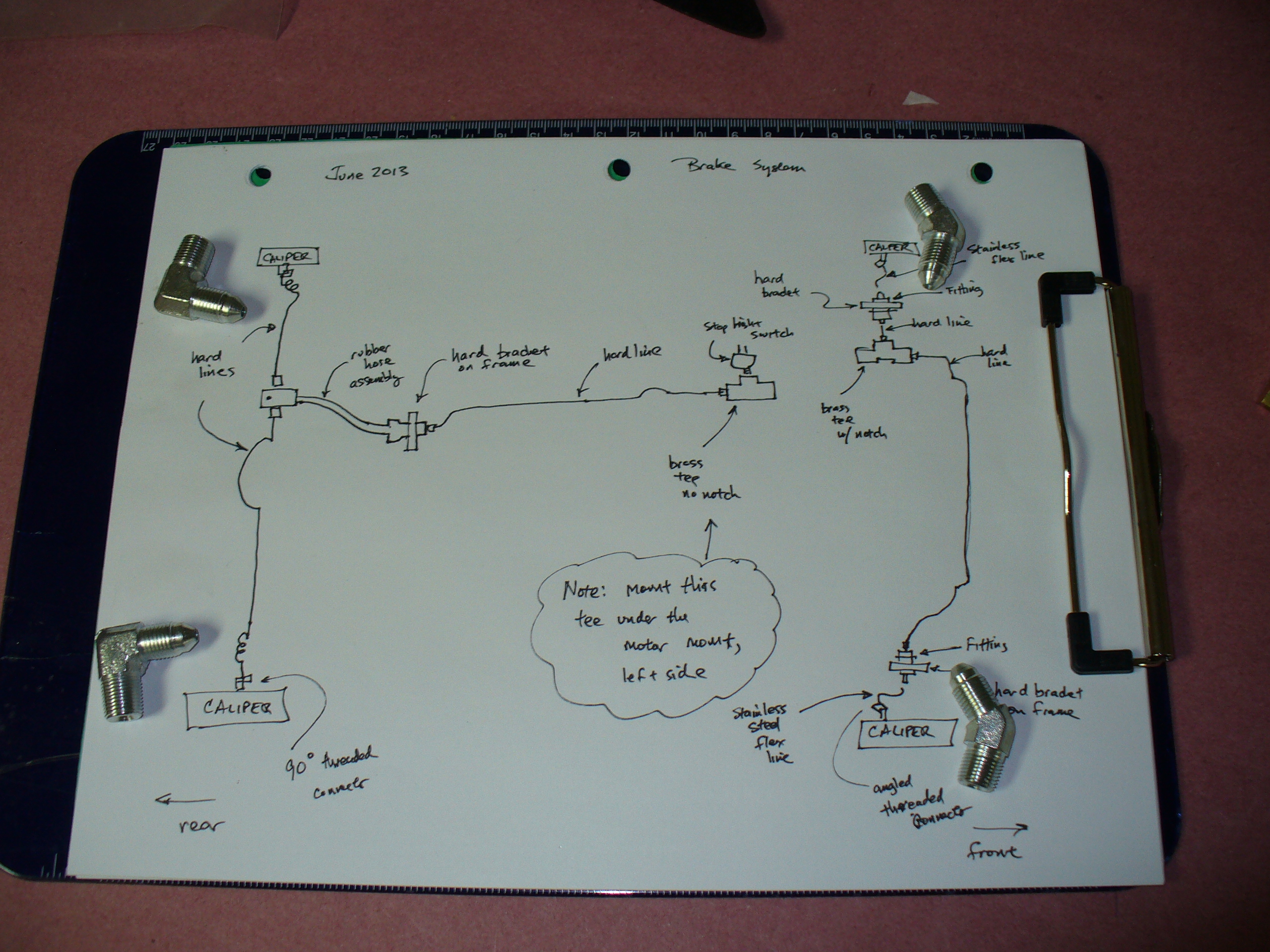
I have been taking my time in this area for a number of reasons. Clearly, the brakes are important, especially on a small car with a powerful engine, and I want to make sure the car is safe. After reading the documentation and talking to the folks at Lone Star and some other guys who have built these cars, I came up with the following overall diagram:

…and here it is with a few of the fittings included. These four fittings are what will go into the sides of the Wilwood calipers themselves.
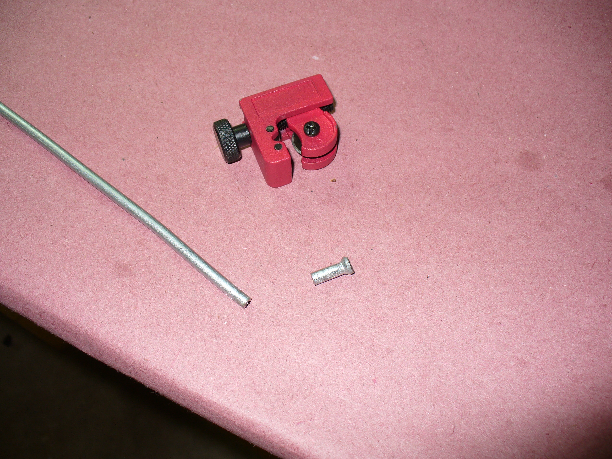
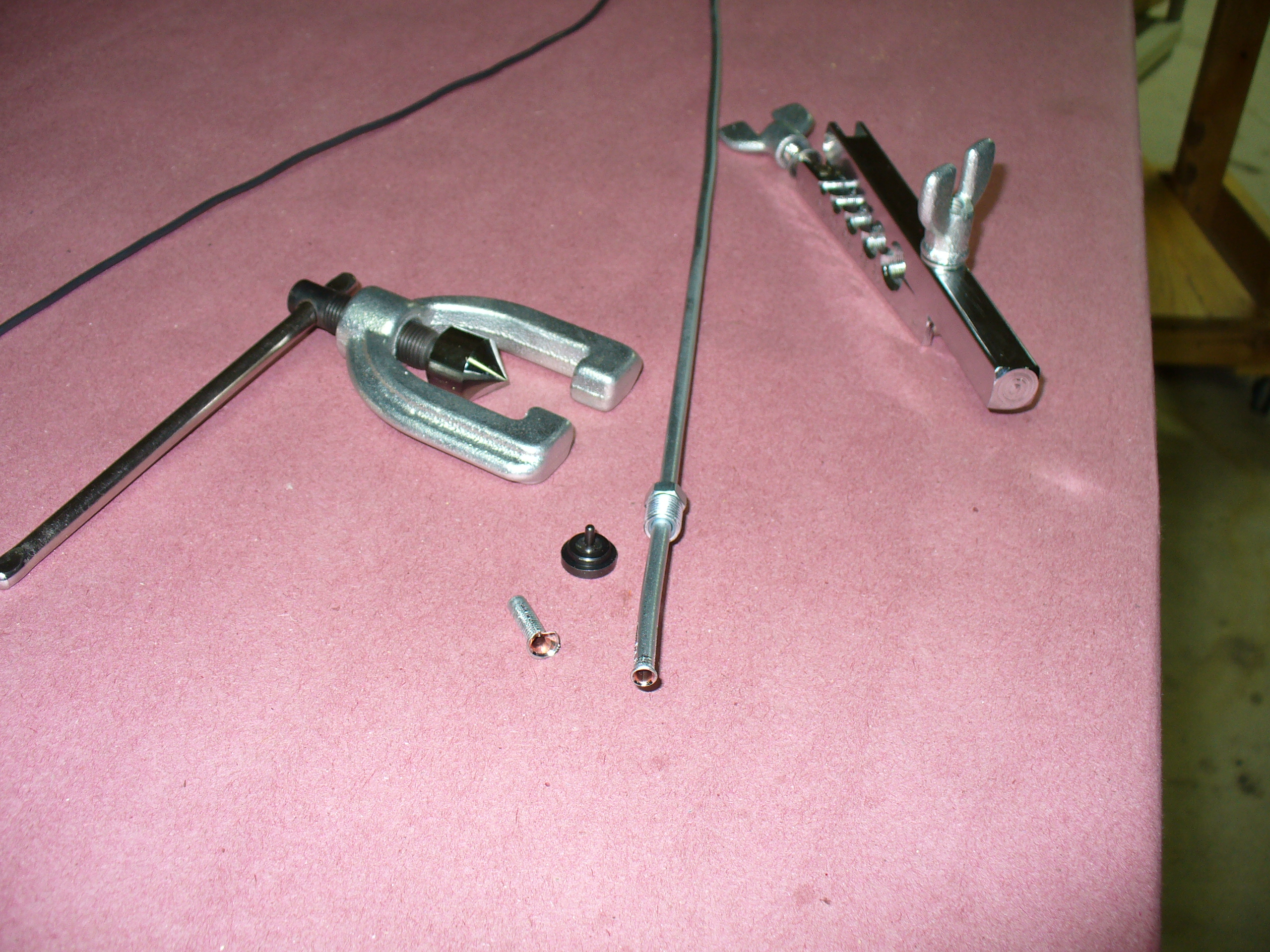
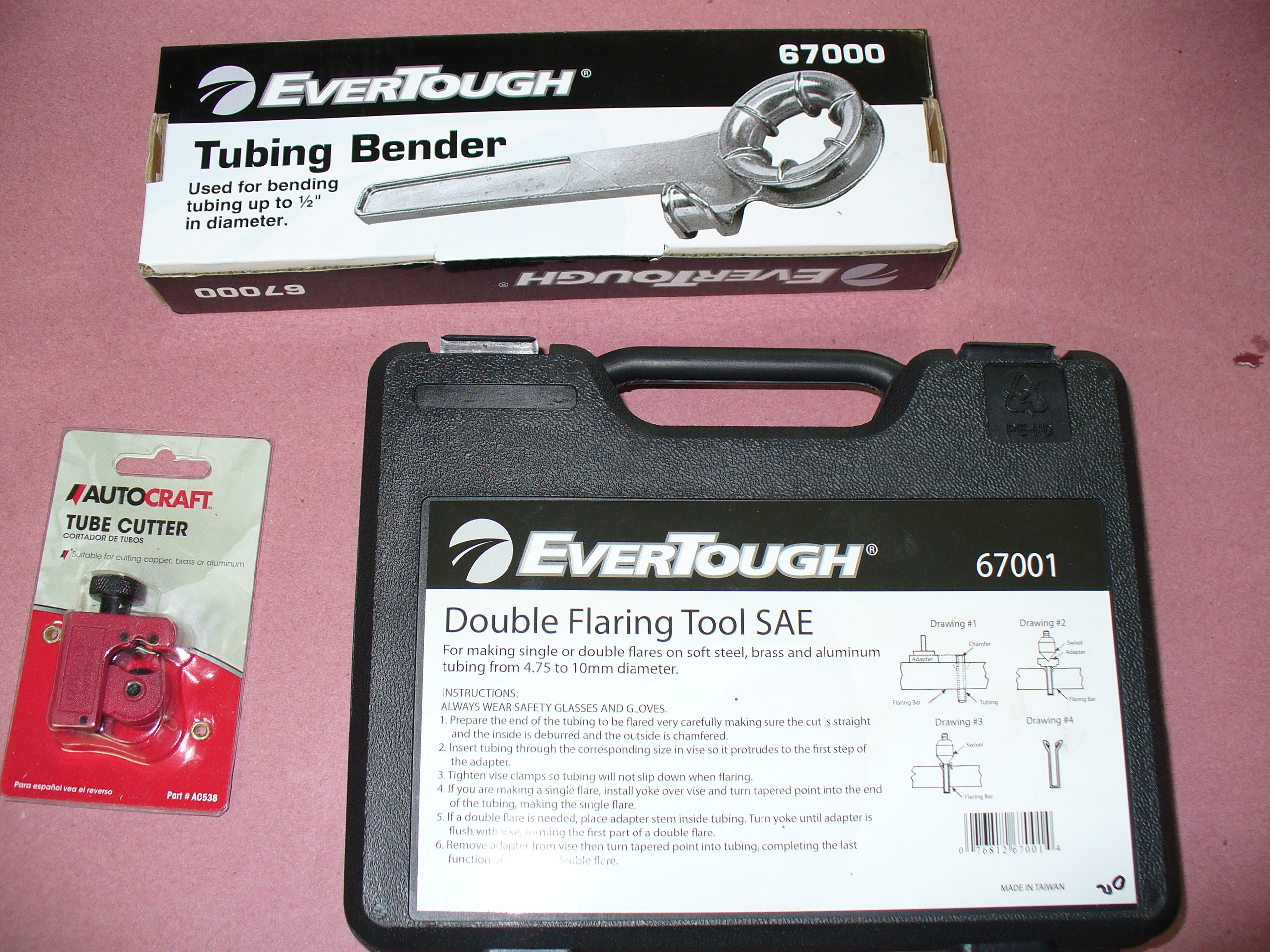
There are a lot of parts, fittings, etc., and I took my time in getting them all organized. I also have some experience in flaring gas lines in residential construction many years ago, so I wanted to flare the brake lines myself. There are a number of great how-to videos on the web talking about the typical double flare approach used for this 3/16 inch flexible tubing, so those were extremely helpful. Here are the tools I purchased for this job:
Here are the various fittings etc. that came with the kit.


These flexible hoses will be used to attach the front calipers to the system. The flexibility allows them to work even as the wheels are being steered from side to side.

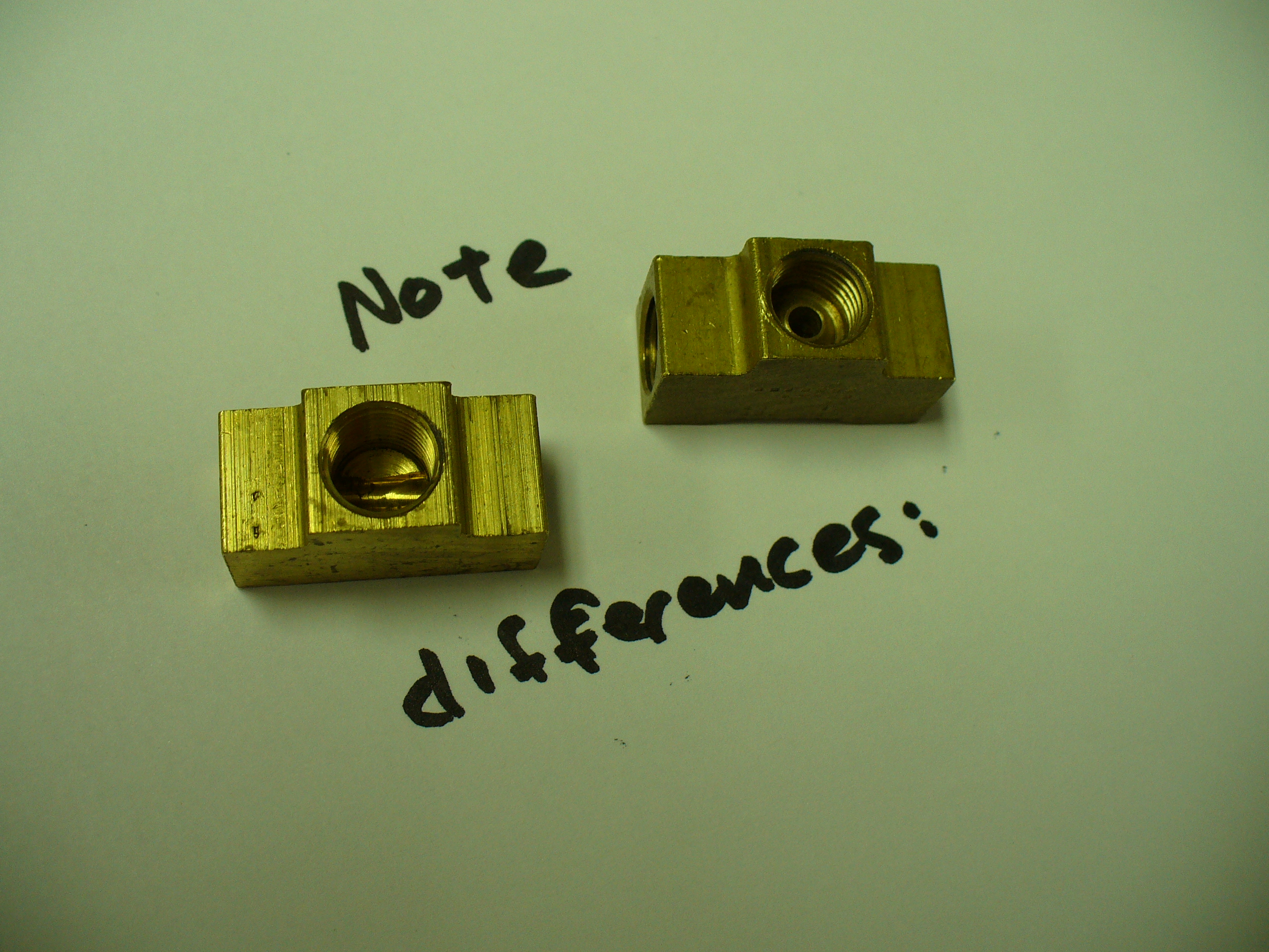
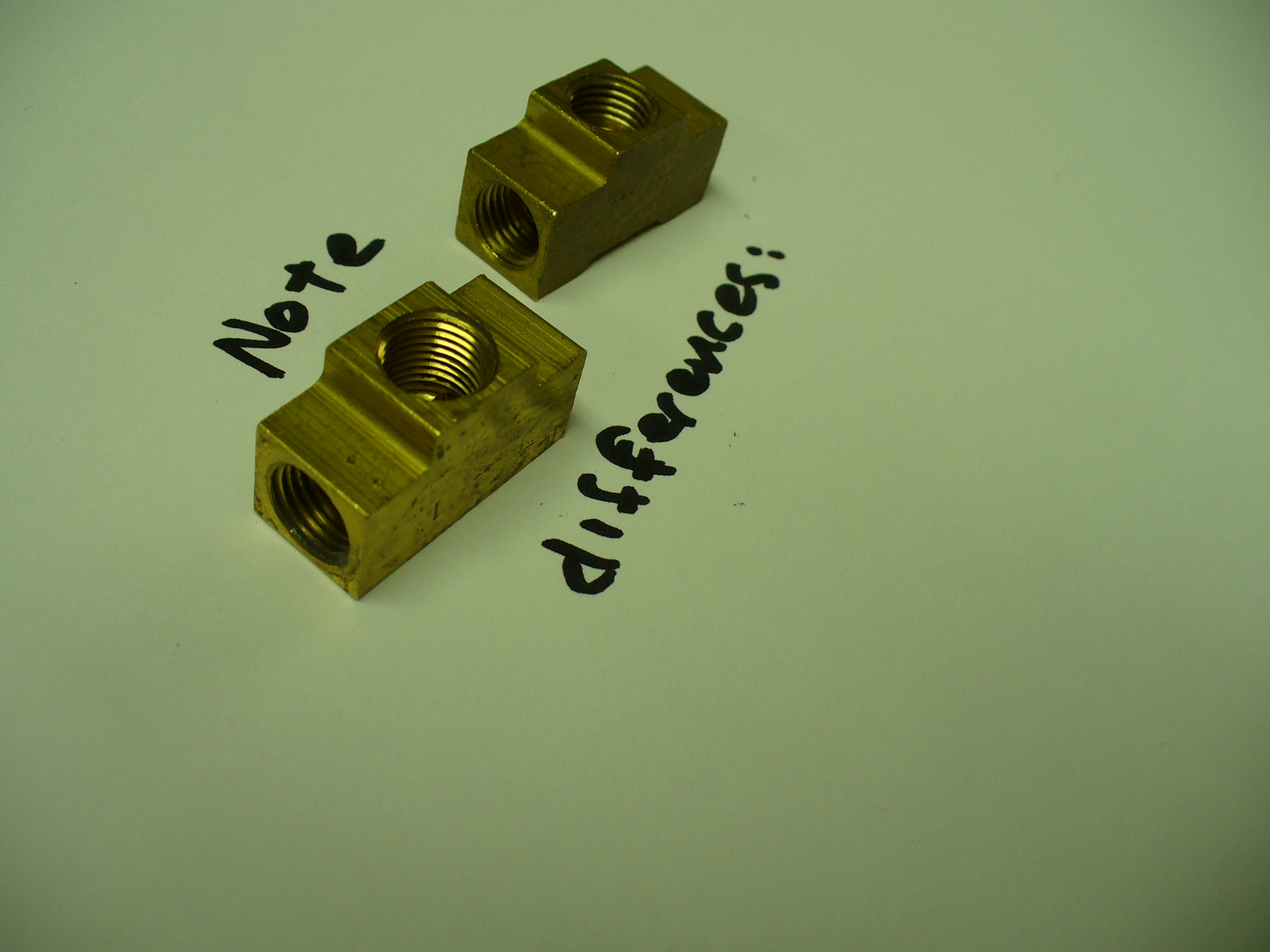
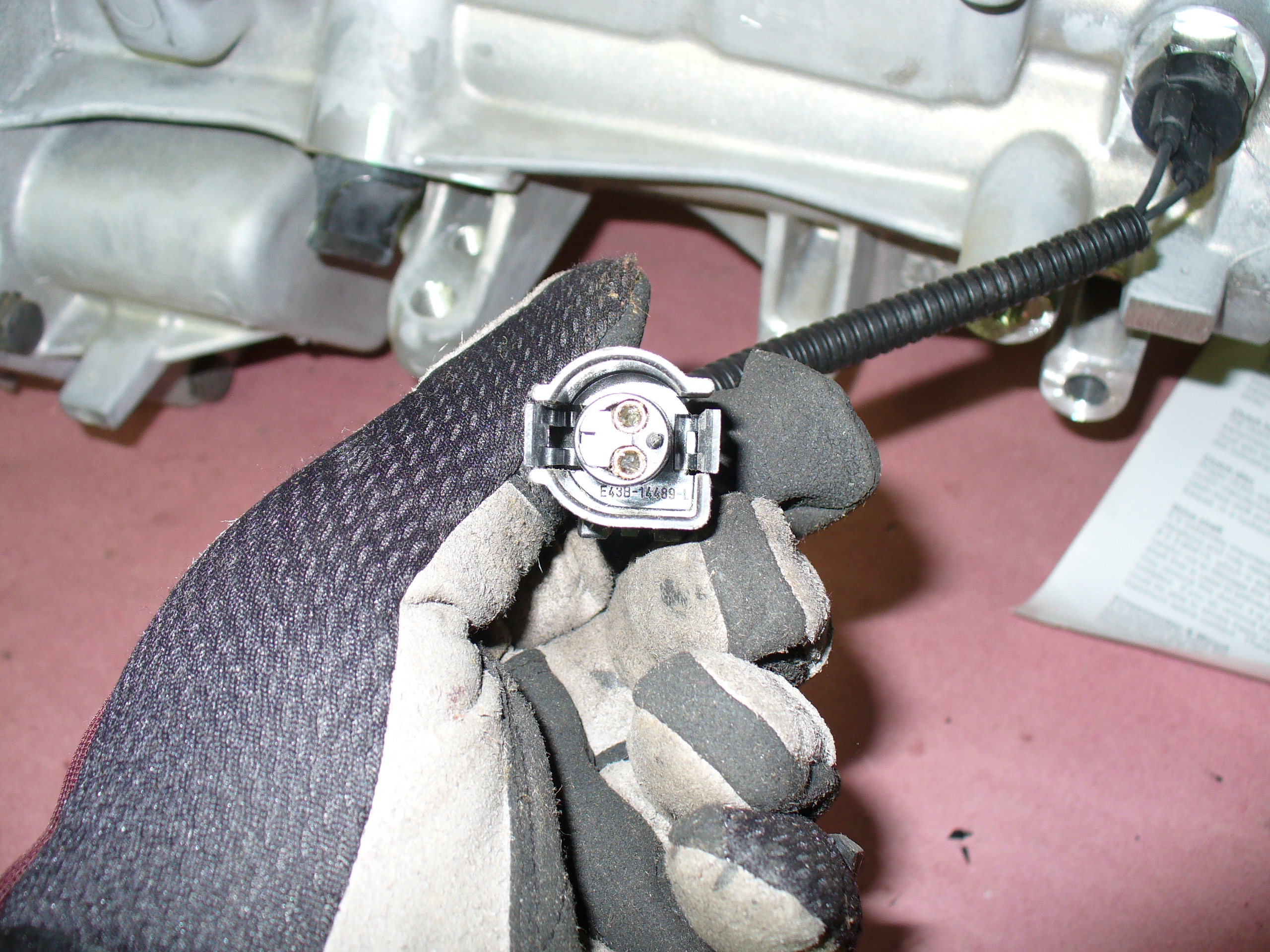
There were two of these brass T-fittings in the kit, and it wasn’t terribly clear which was which. After some detective work and a few calls to LSC and others, I learned that the one on the left is for the brake light sensor, and the one on the right is the T that joins the two front wheels’ brakes together.


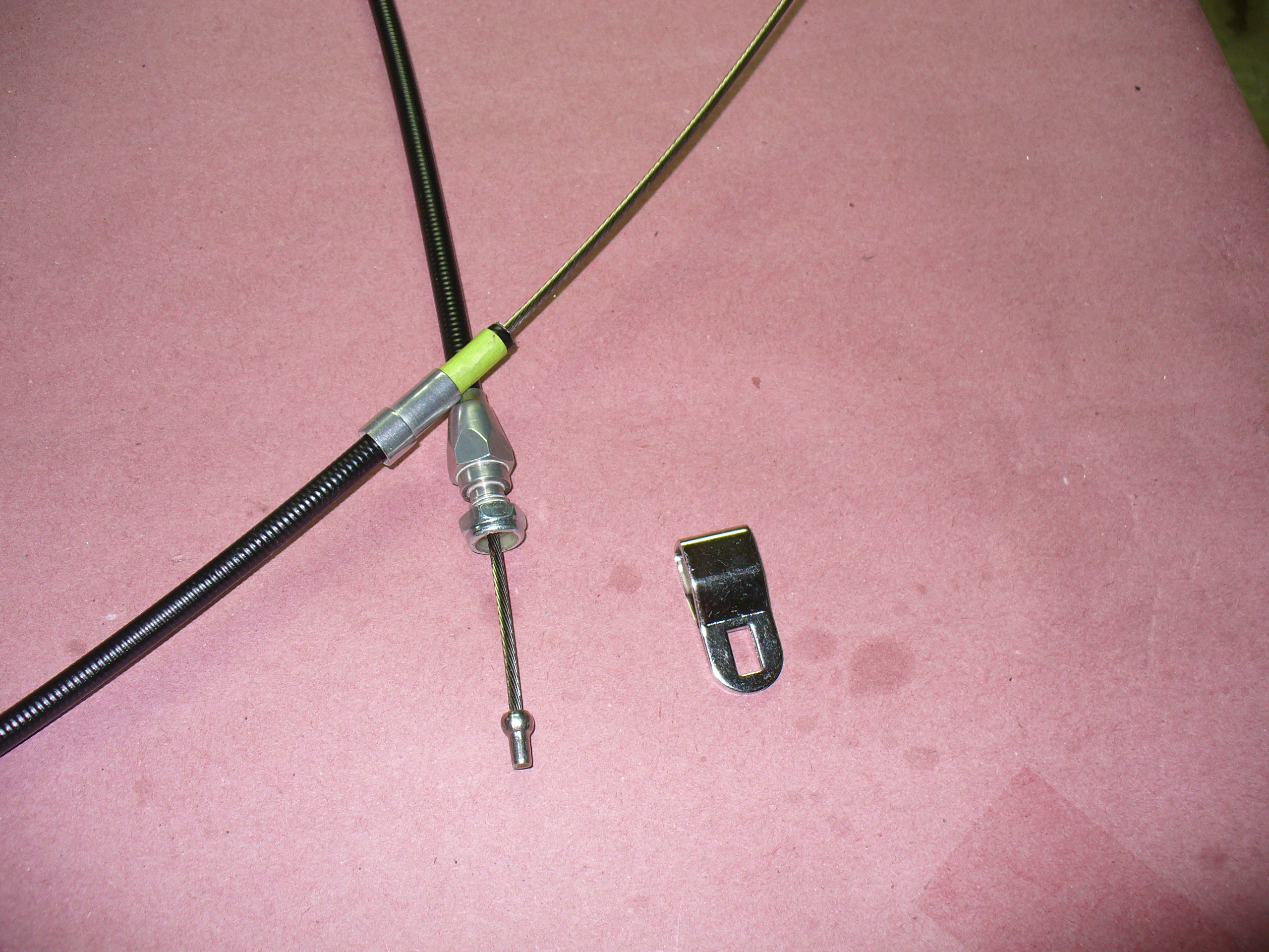
This brake line is for the rear. It is flexible because it will run from a hard point on the frame to the top of the differential, which will move up and down with changes in the road surface. The T-fitting shown on the right allows lines to be run out to each of the two rear calipers.
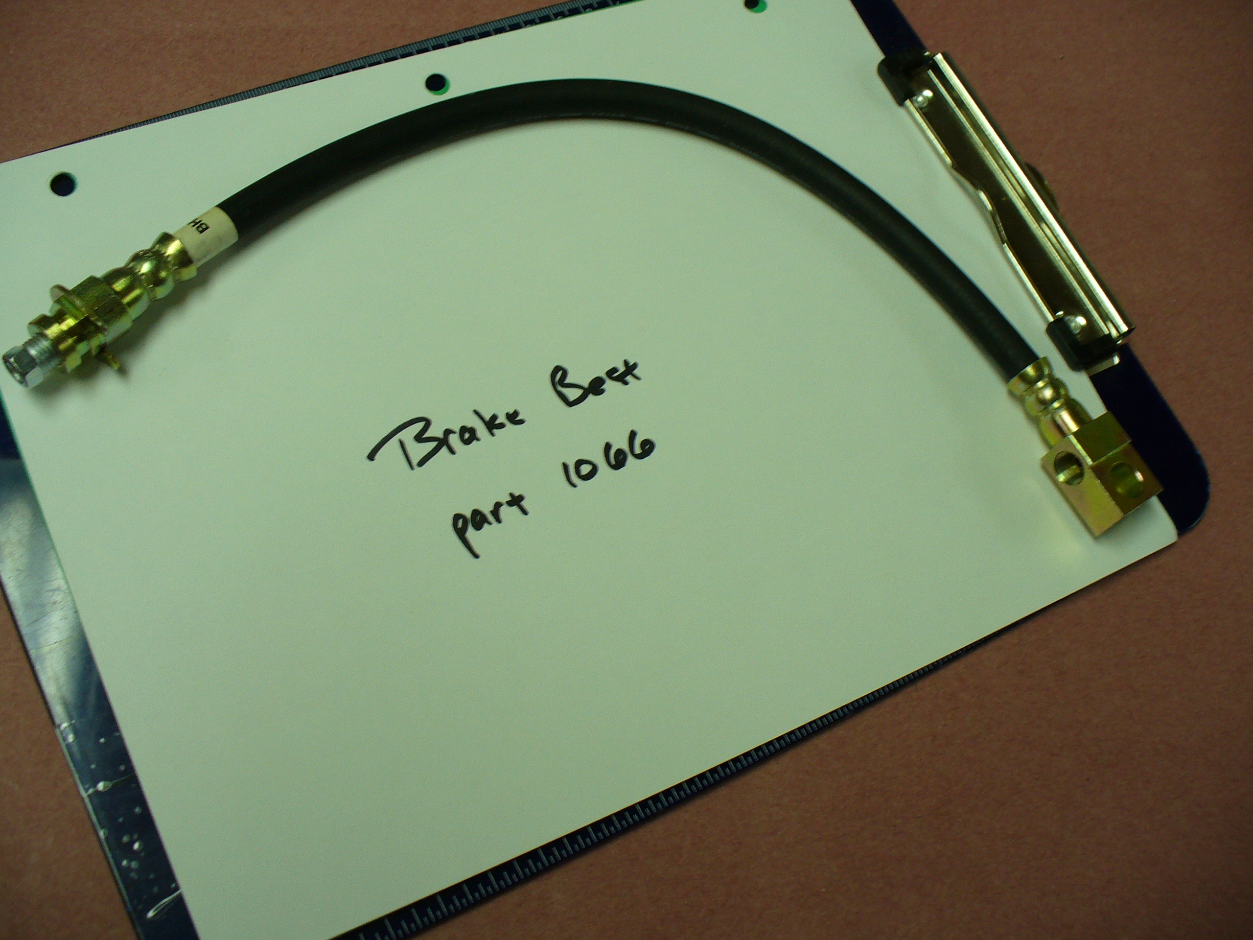
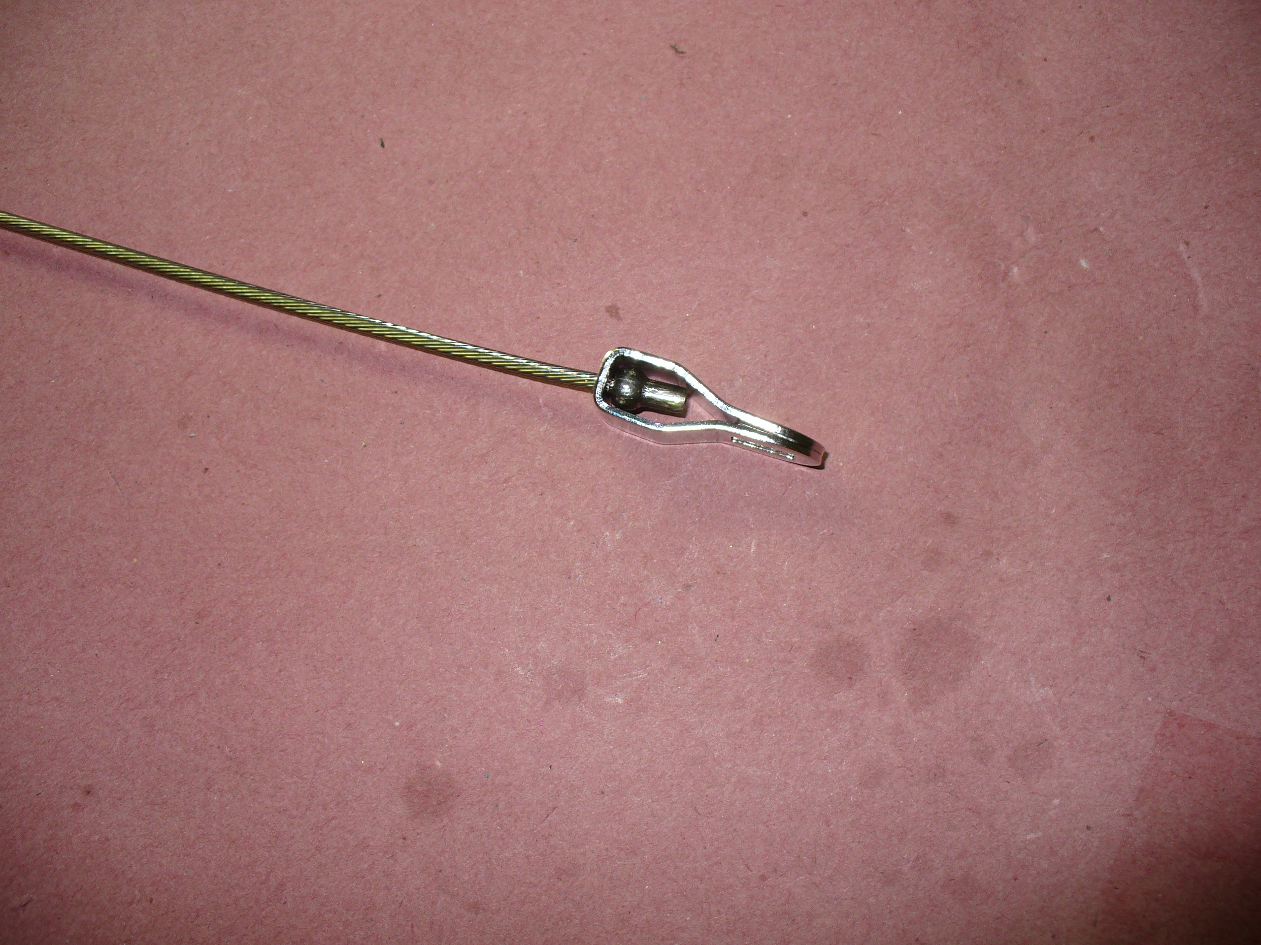
This end will bolt to the panhard bar bracket on the differential:

…and this end connects to the hard point on the frame.

Again: nice set of nuts and bolts and c-clips, all organized for this project. There were some missing items that would have been nice to have: the e-clips needed for the brake adapter parts as well as the bolt and nuts needed to attach the rear flexible line to the differential bracket.

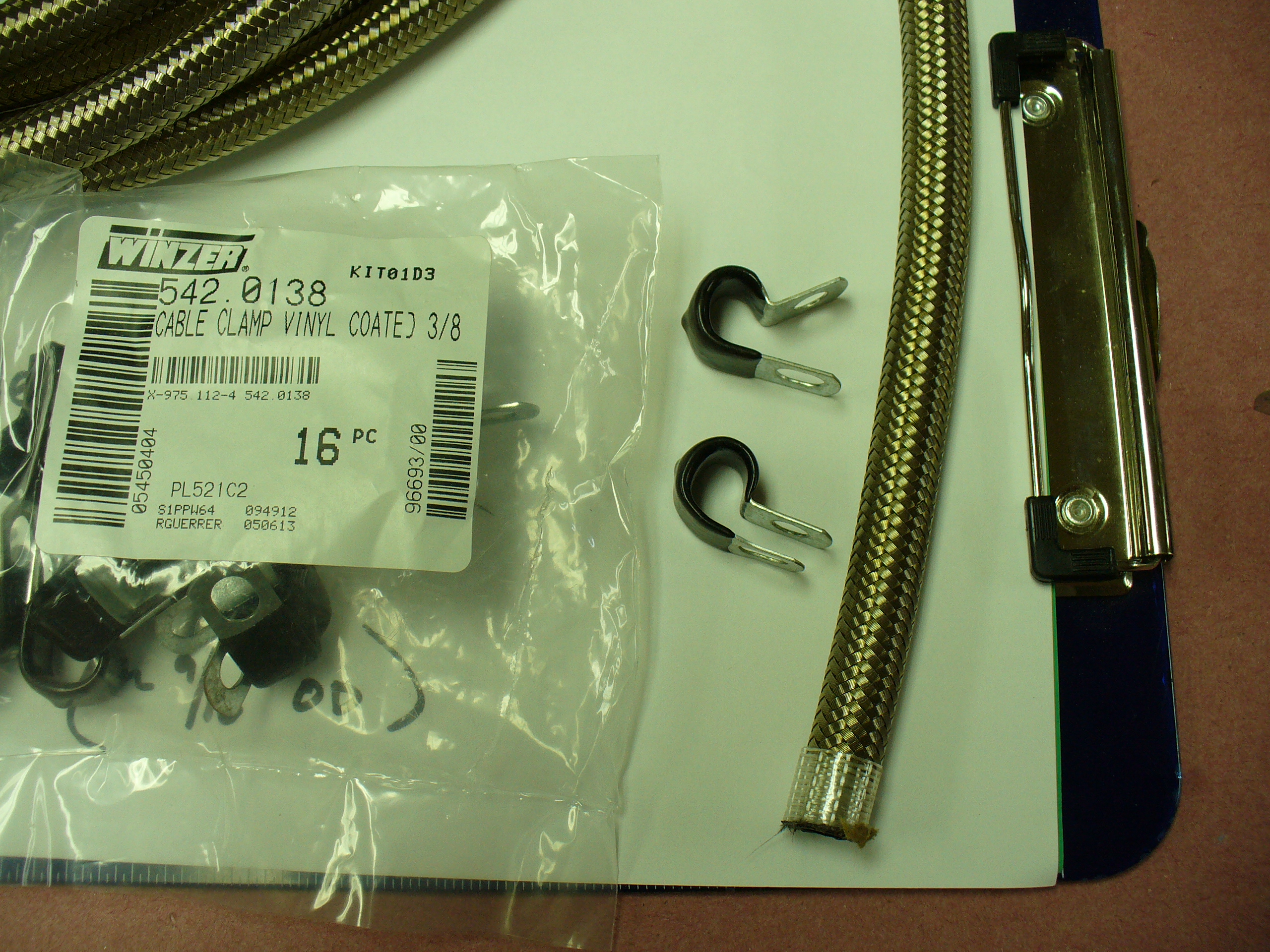
Here is the fuel line. It has a larger diameter than the c-clips above anticipated, so I will need to go out and buy some larger c-clips to attach this to the frame. The good news is that it is flexible and seems to be of good quality, so line resistance should be low and it should be relatively easy to install.

These 3/8 inch c-clips clearly won’t be able to fit around this fuel line easily:
Exciting stuff! More to come soon…
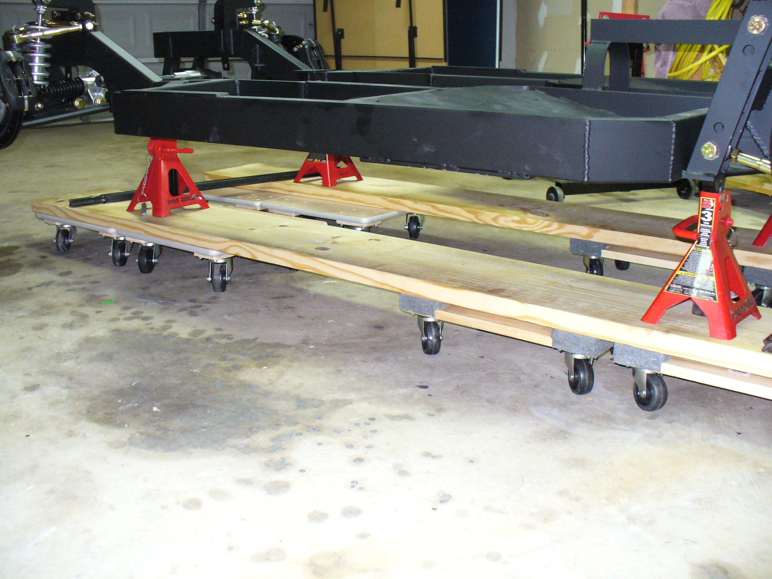
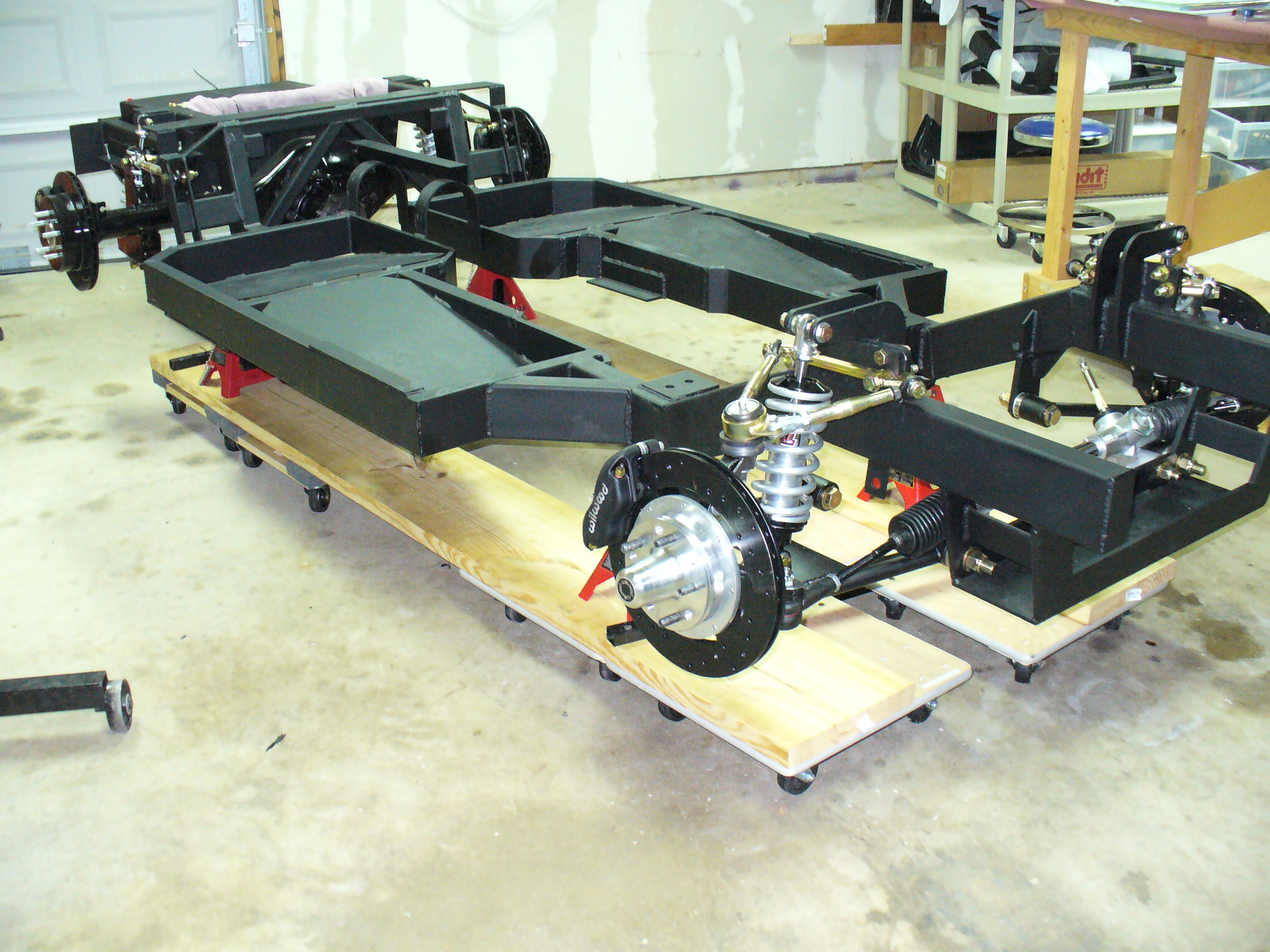
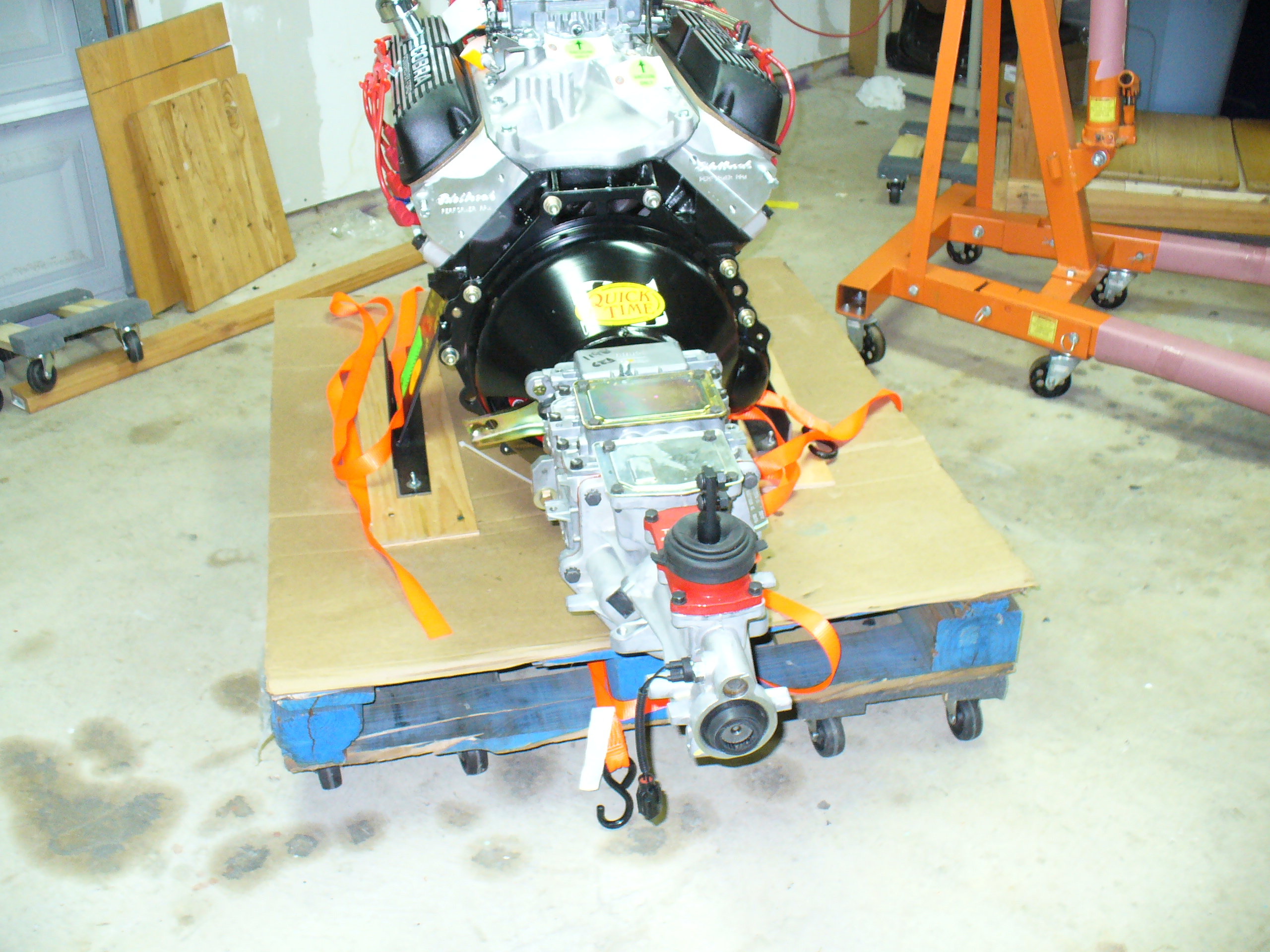
After mating the engine and transmission, one of the key next steps is putting that assembly into the chassis. However, looking at my rolling rack for my chassis, I can see how it might be hard to roll around once that happens, so I decided to rebuild it to take more weight.
As you can see, I am using two 8-foot 2×12’s and supporting them with extra moving dollies. Each of these moving dollies can allegedly support 1,000 pounds, and with eight of them under the chassis now I could probably park my F-150 on top of the assembled Cobra if I wanted to! I won’t be doing that, btw…

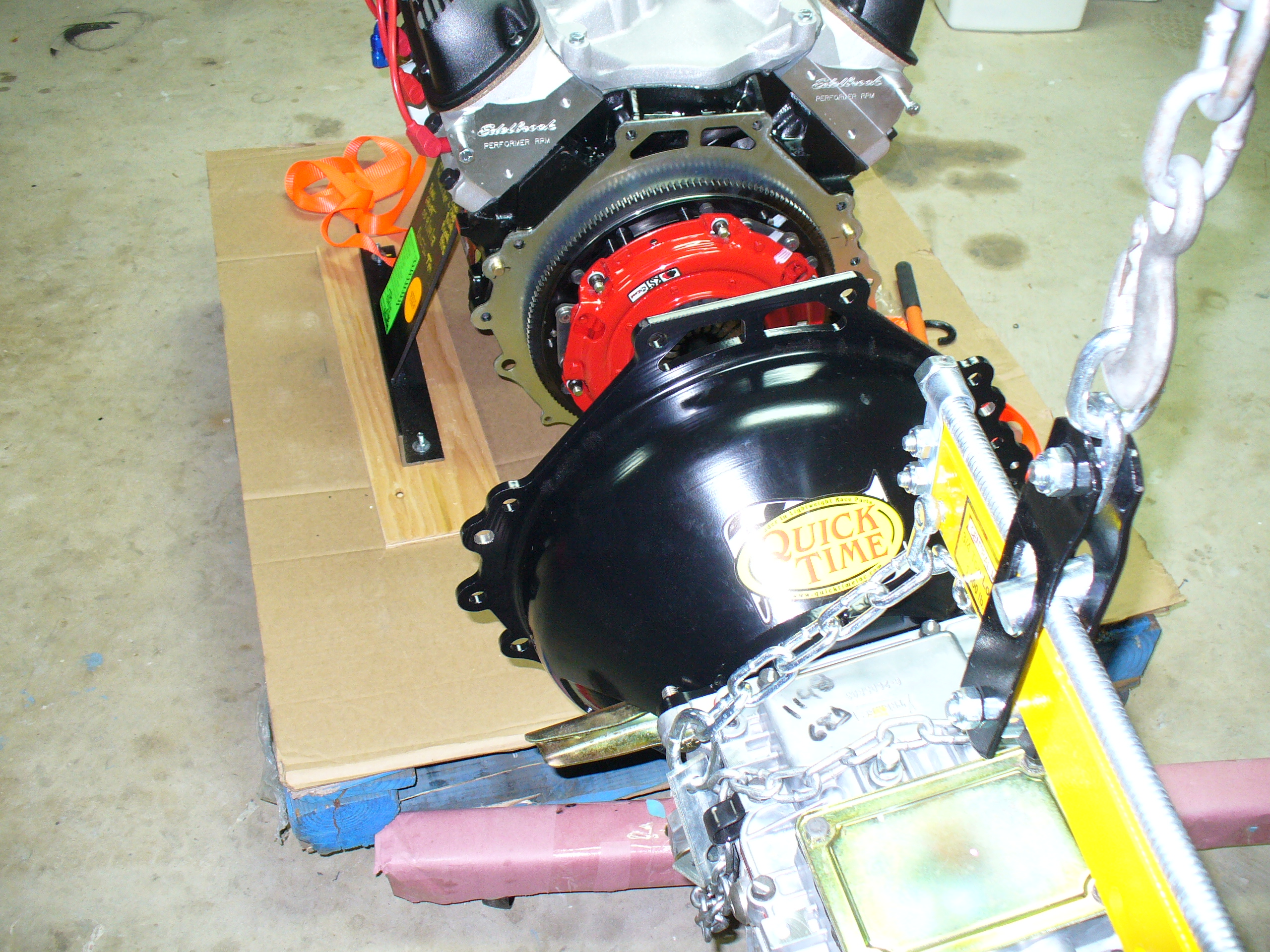
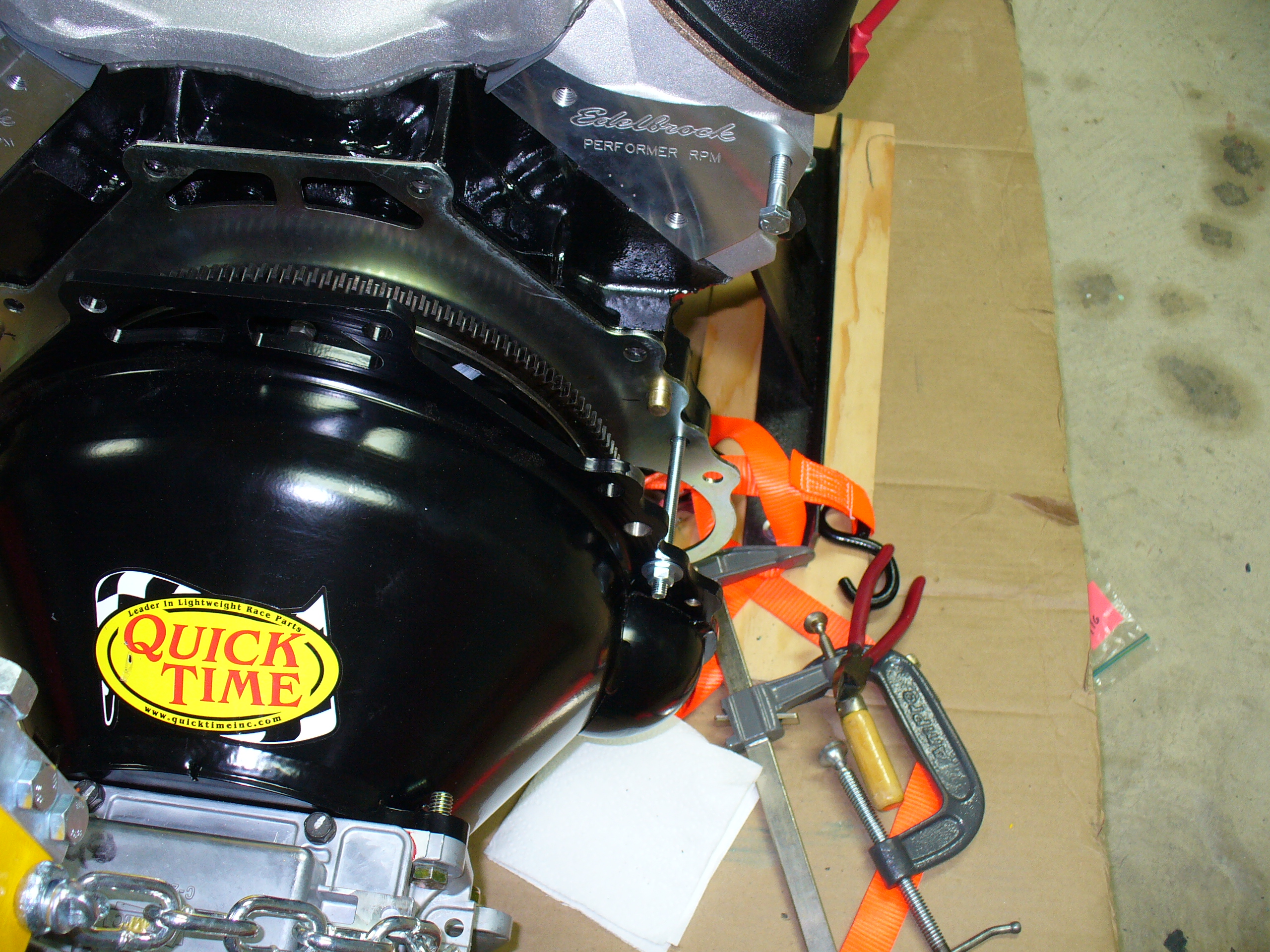
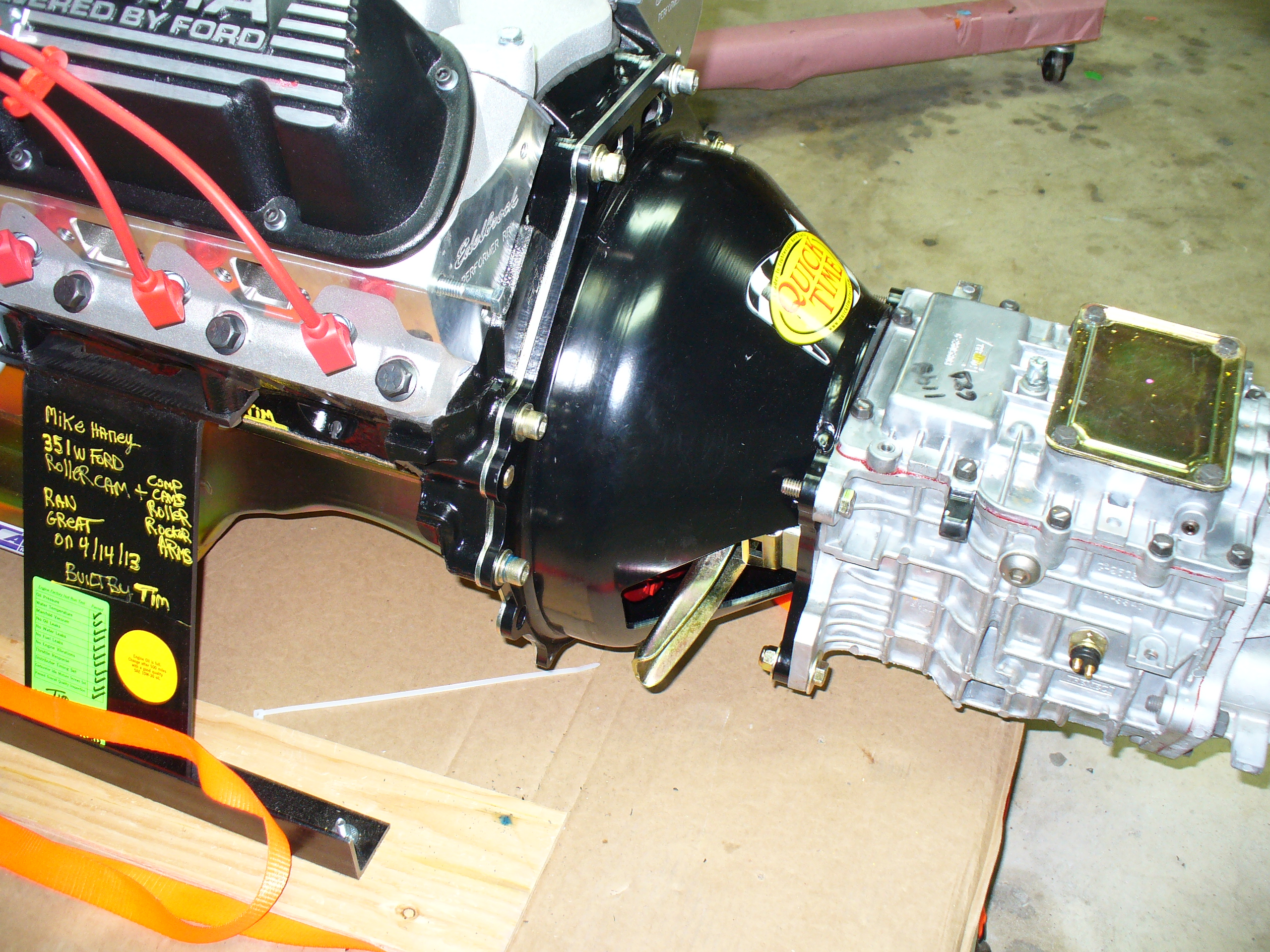
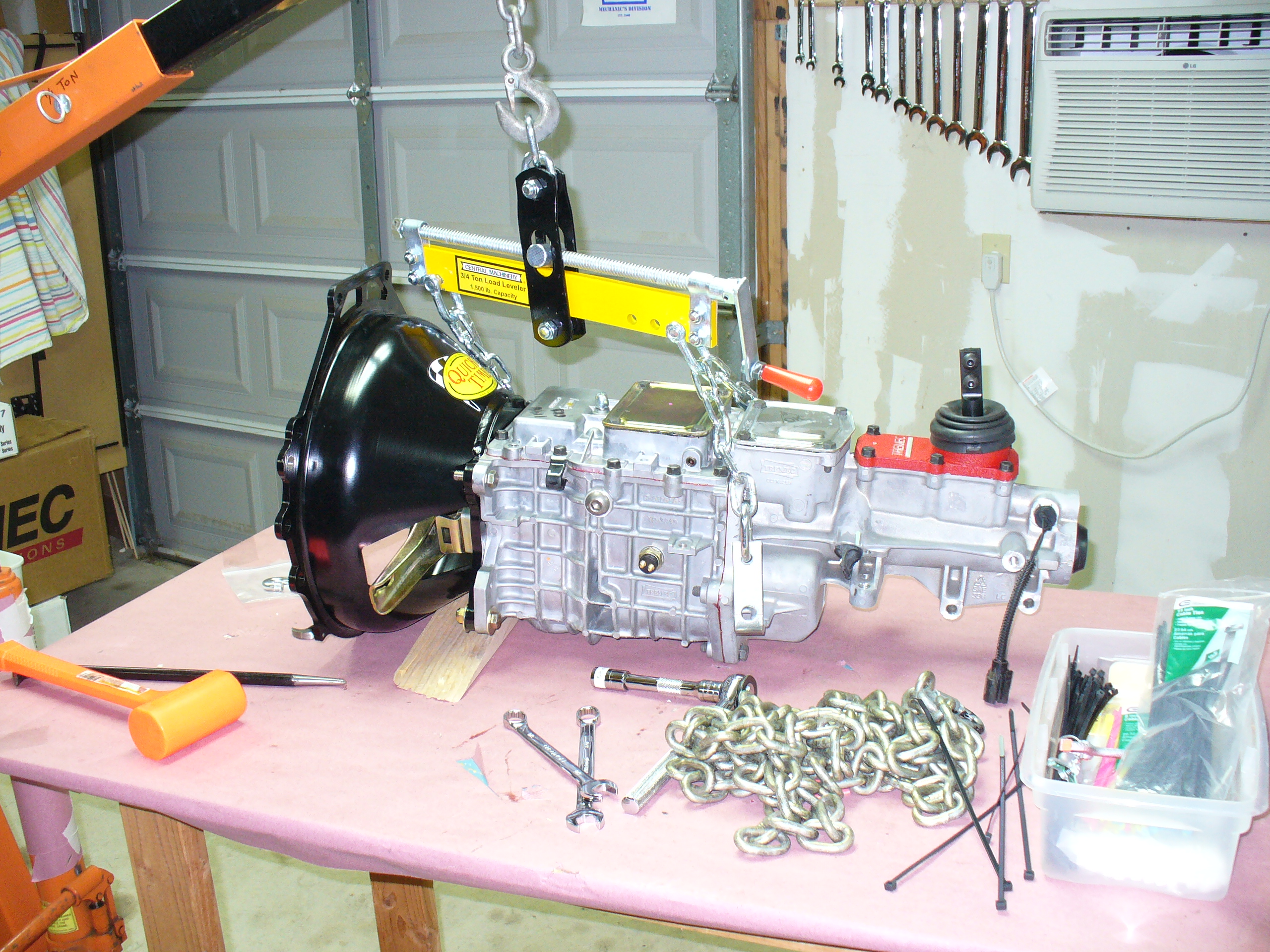
Also done this weekend: completing the assembly of the engine to the transmission!
Here is the task: put these two bits together:


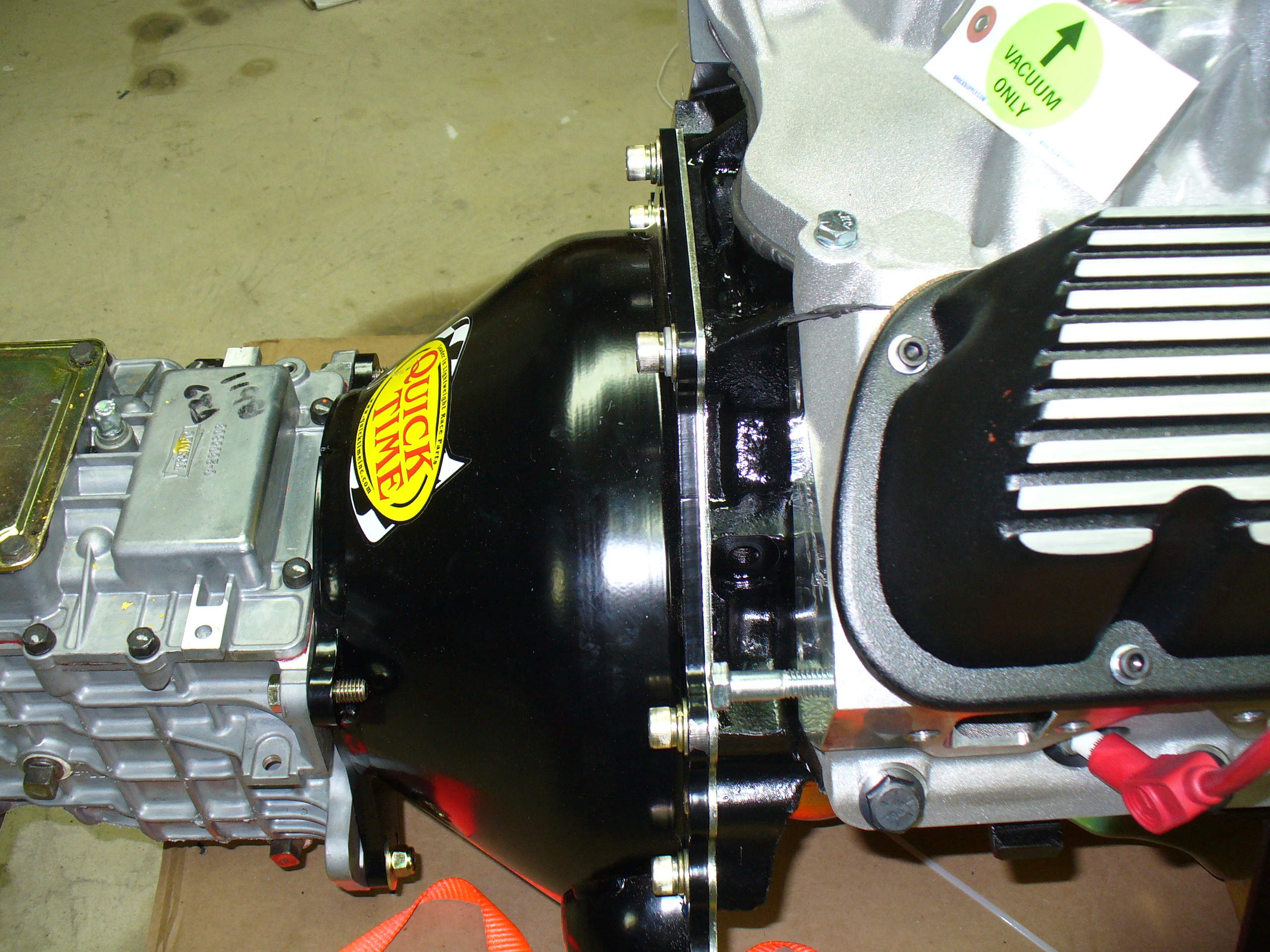
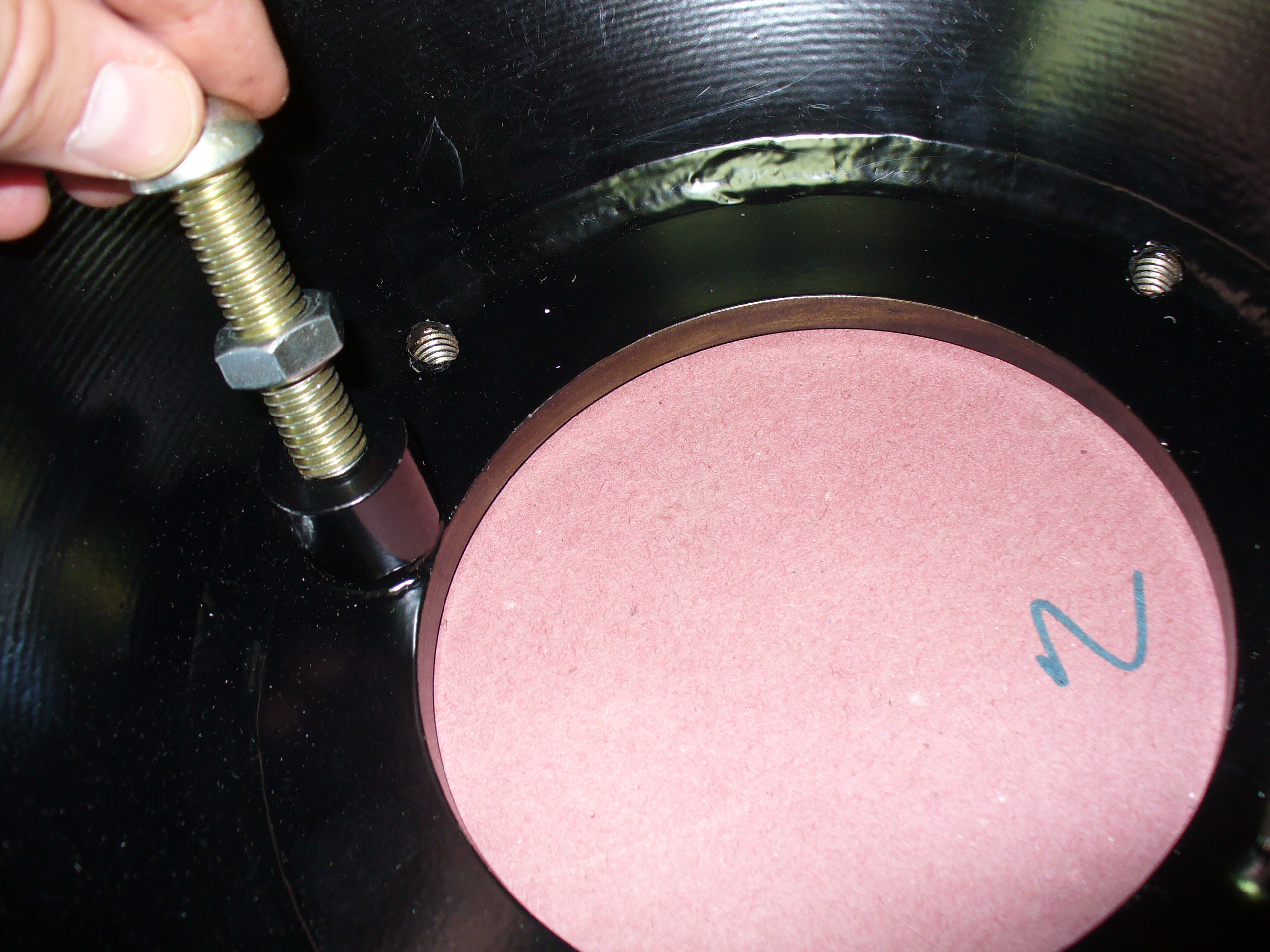
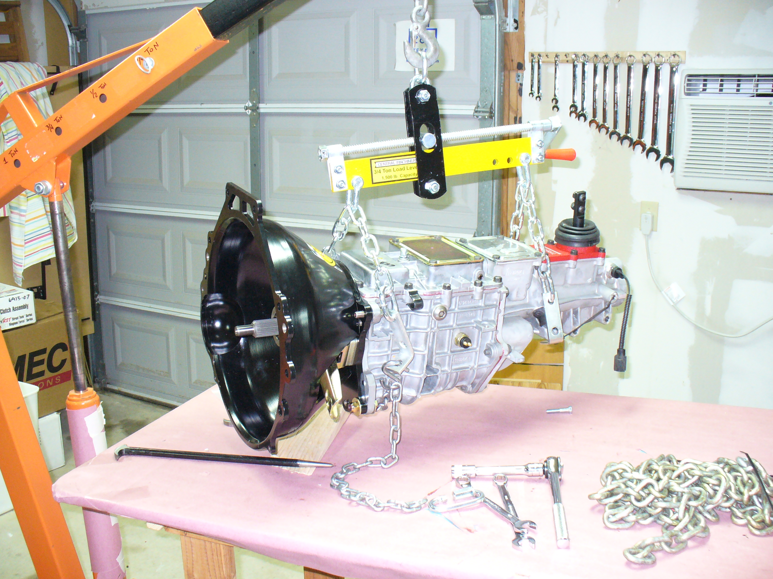
Tried several methods to get the two pieces to align.

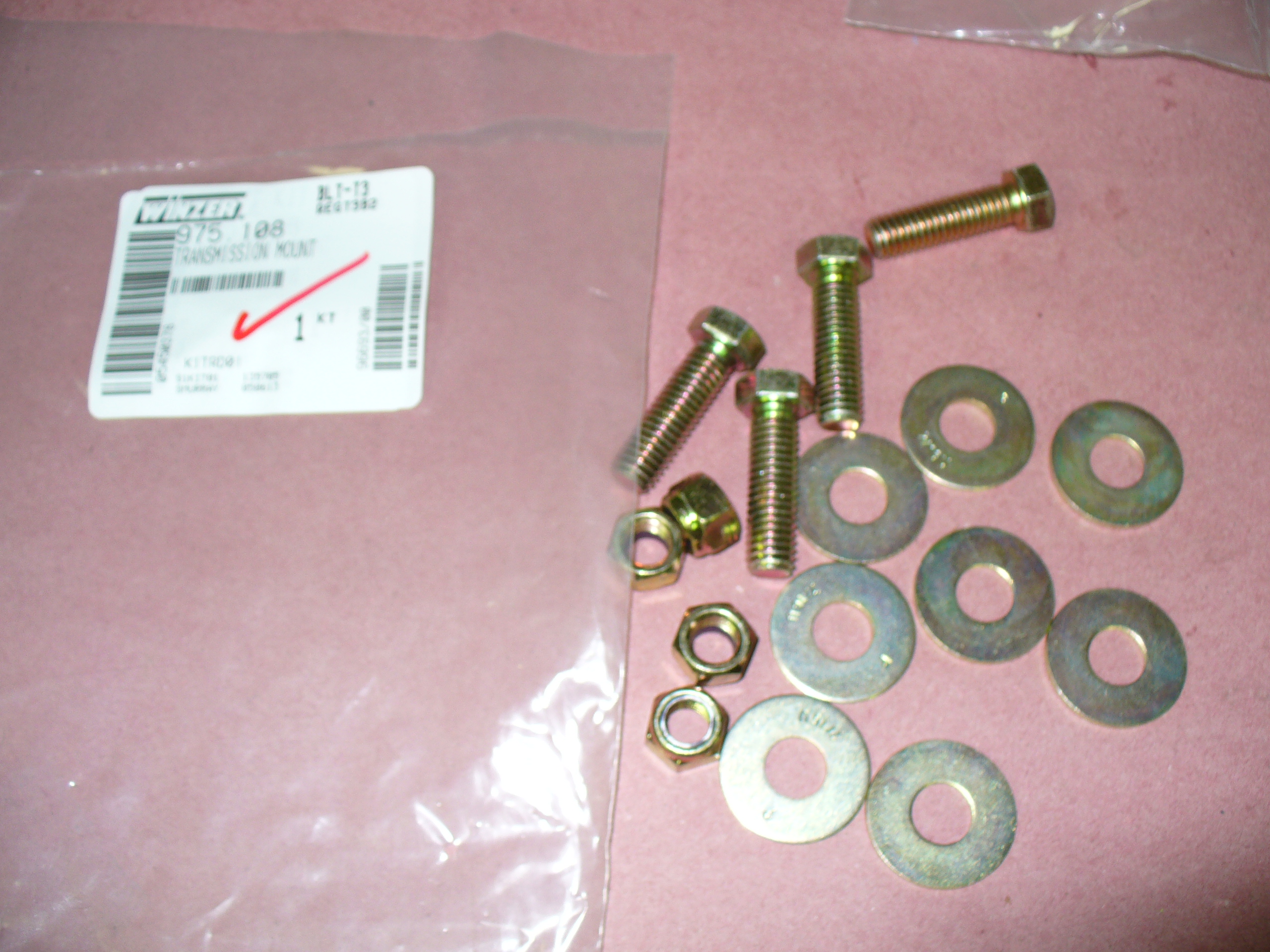
Ended up using two of these nut and bolt assemblies to line up the holes, then slowly tighten them together.


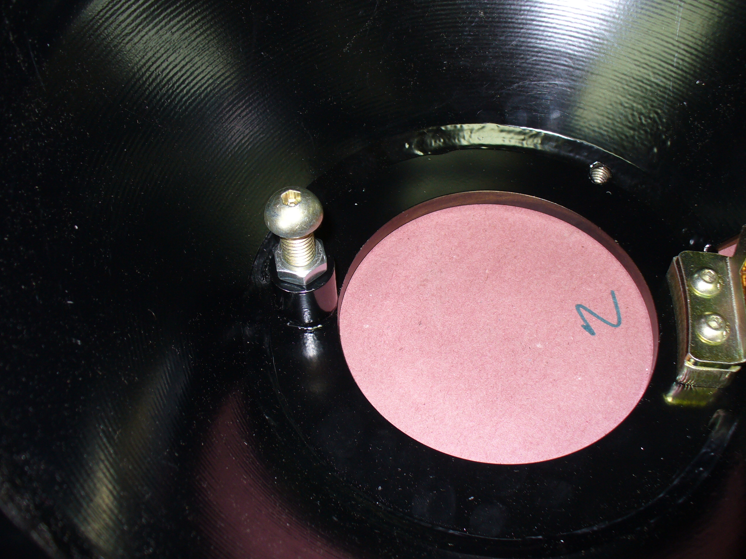
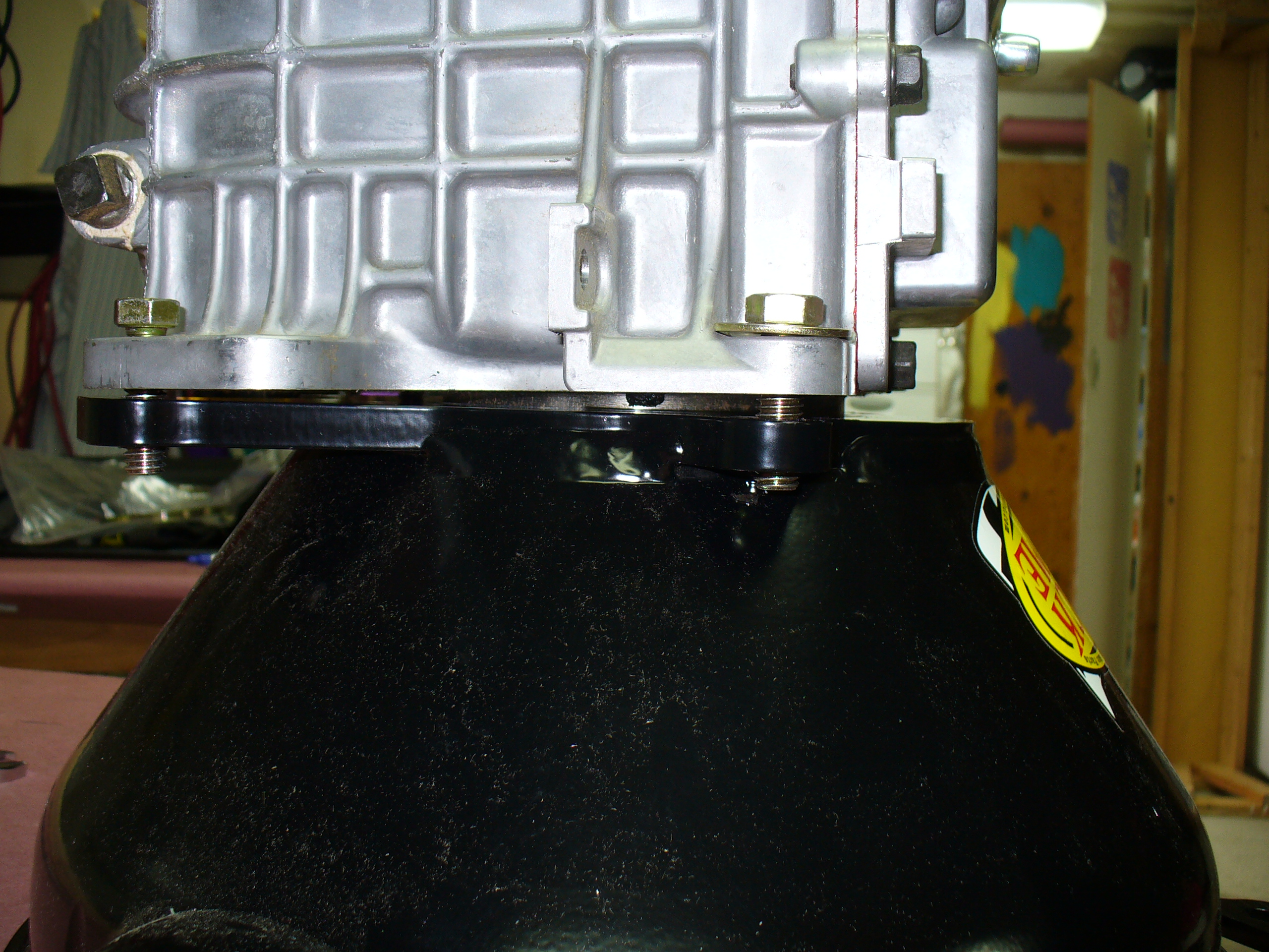
Nice and tight fit — after a lot of fiddling around.

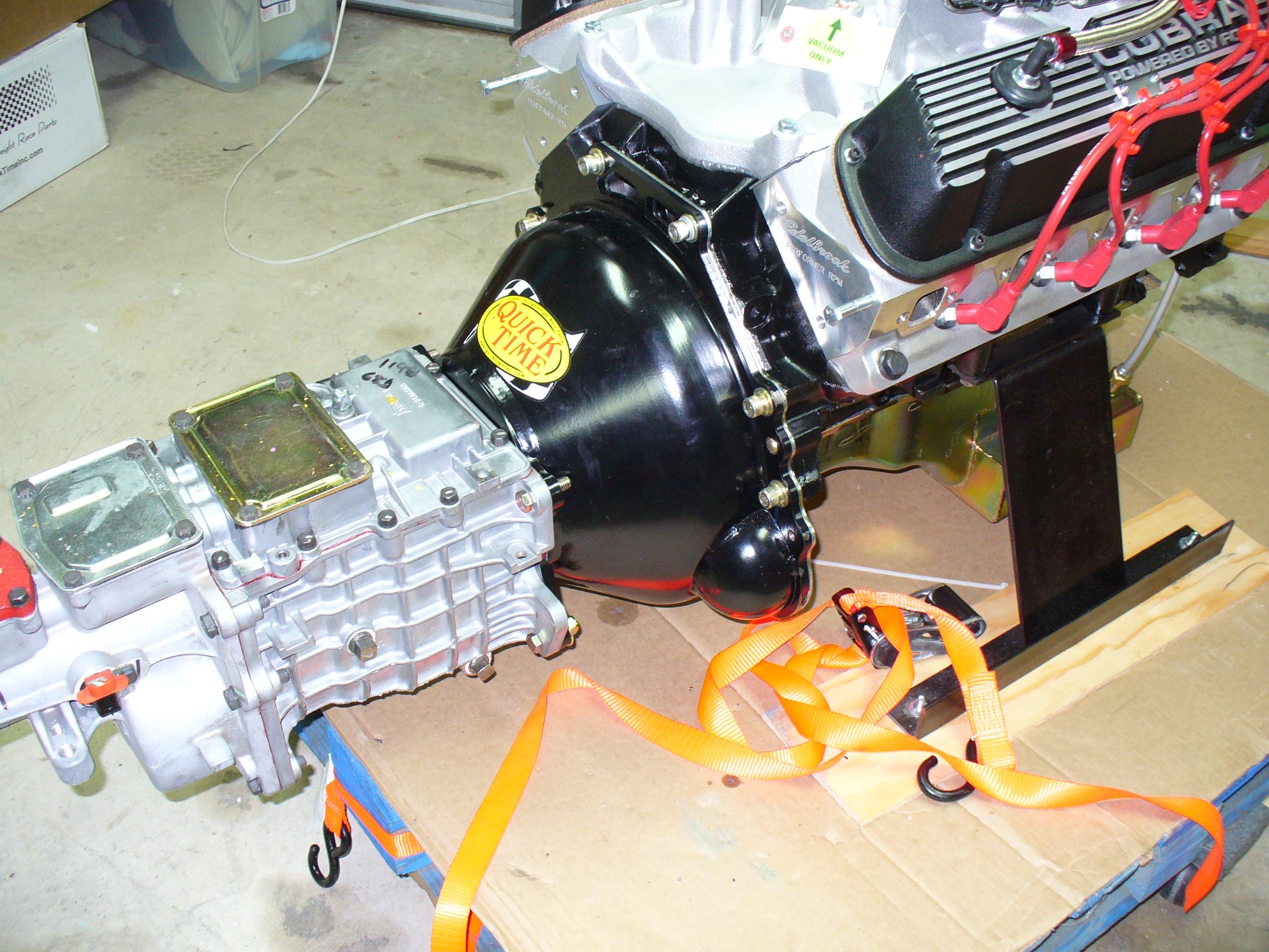
All assembled and ready to go! Next stop: into the chassis…
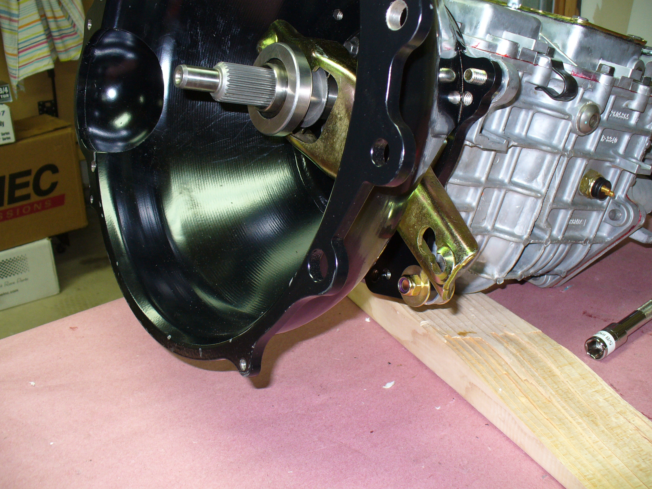
This weekend I mated up the transmission to the bell housing.
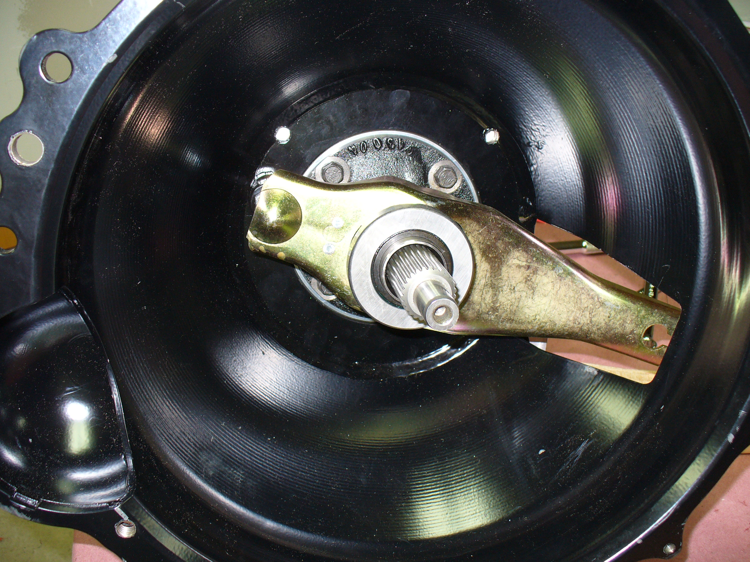
I attached this bracket to the inside of the housing…


…and then this pivot bolt.
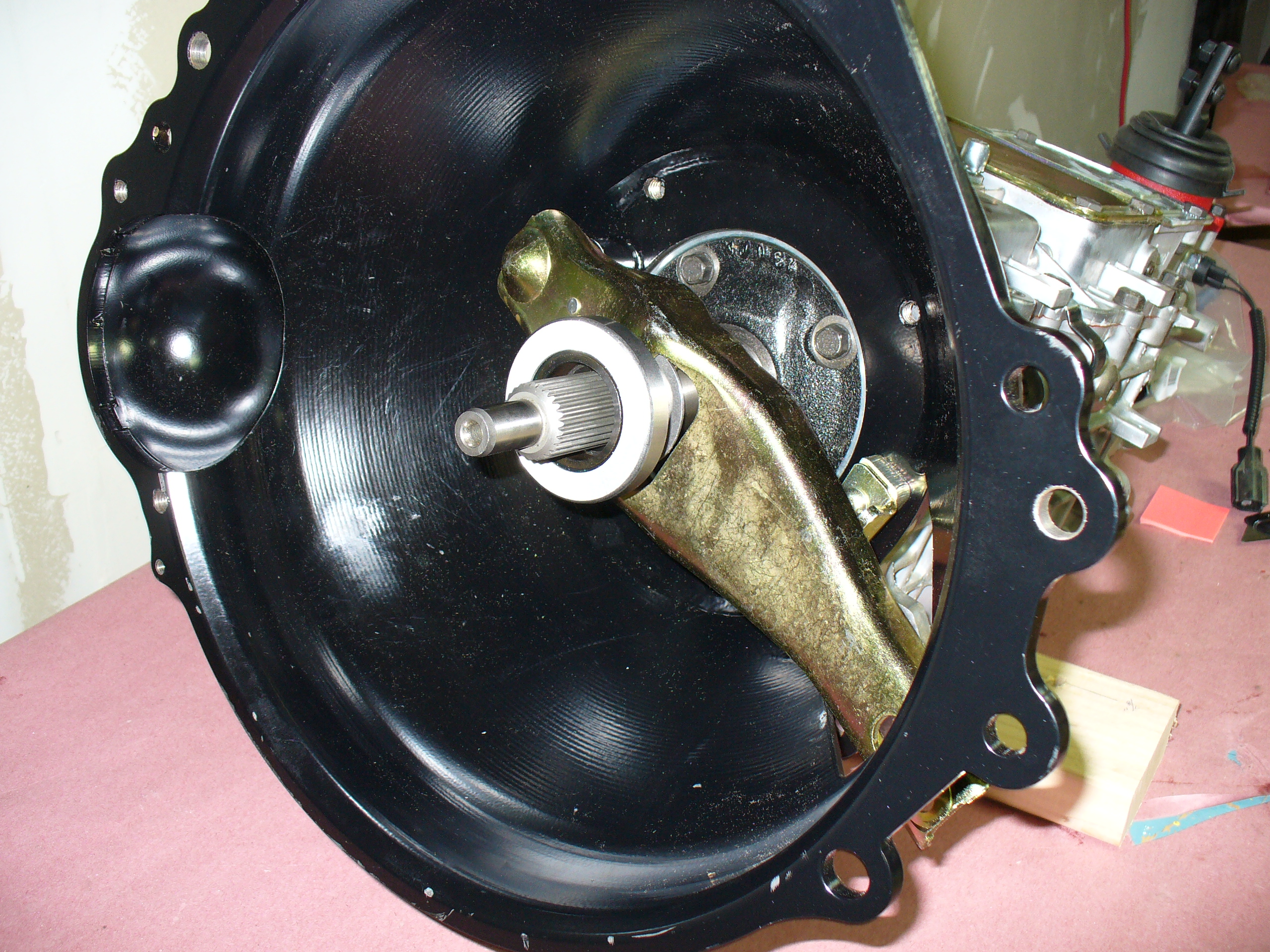
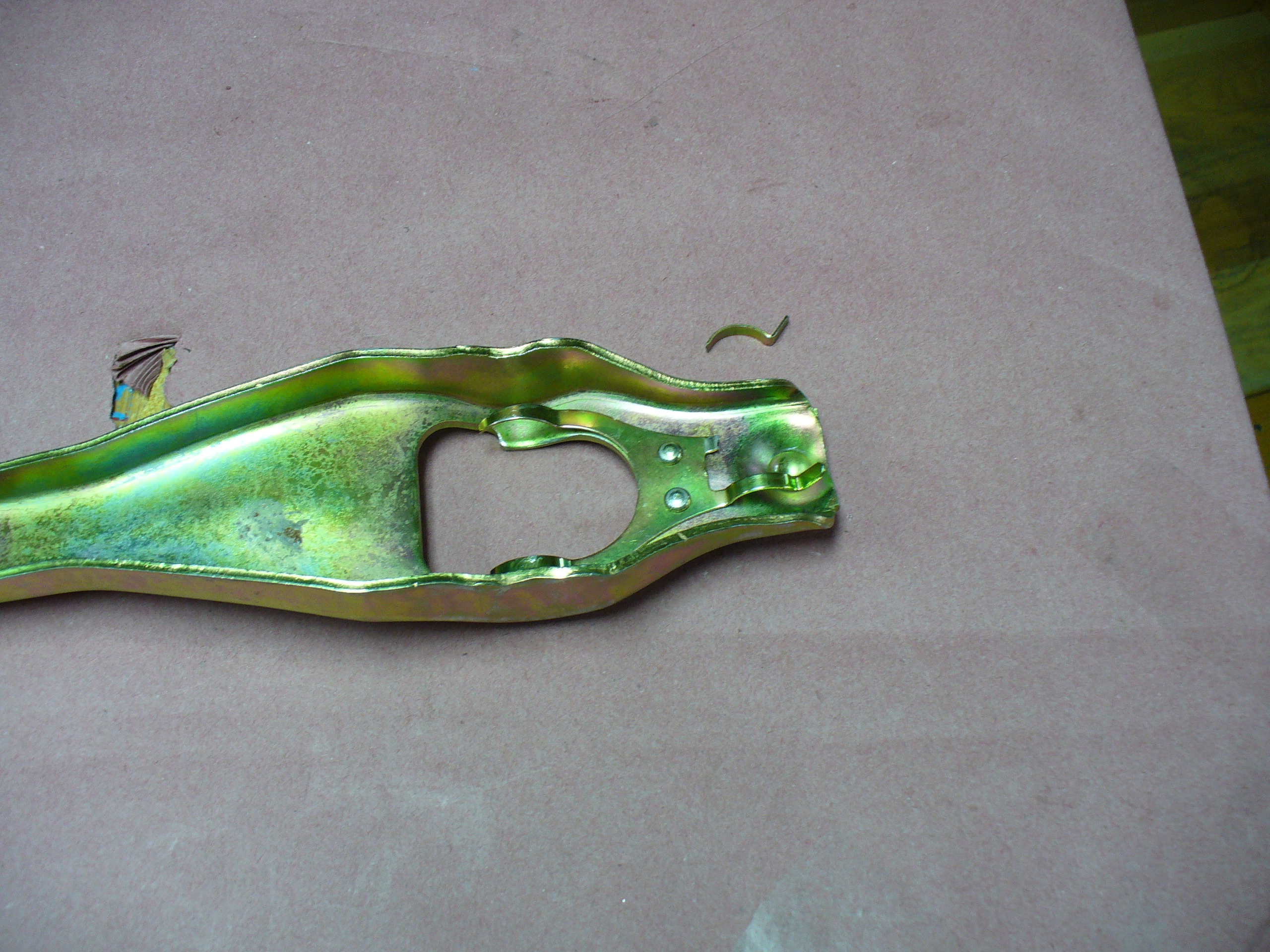
This is the fork.


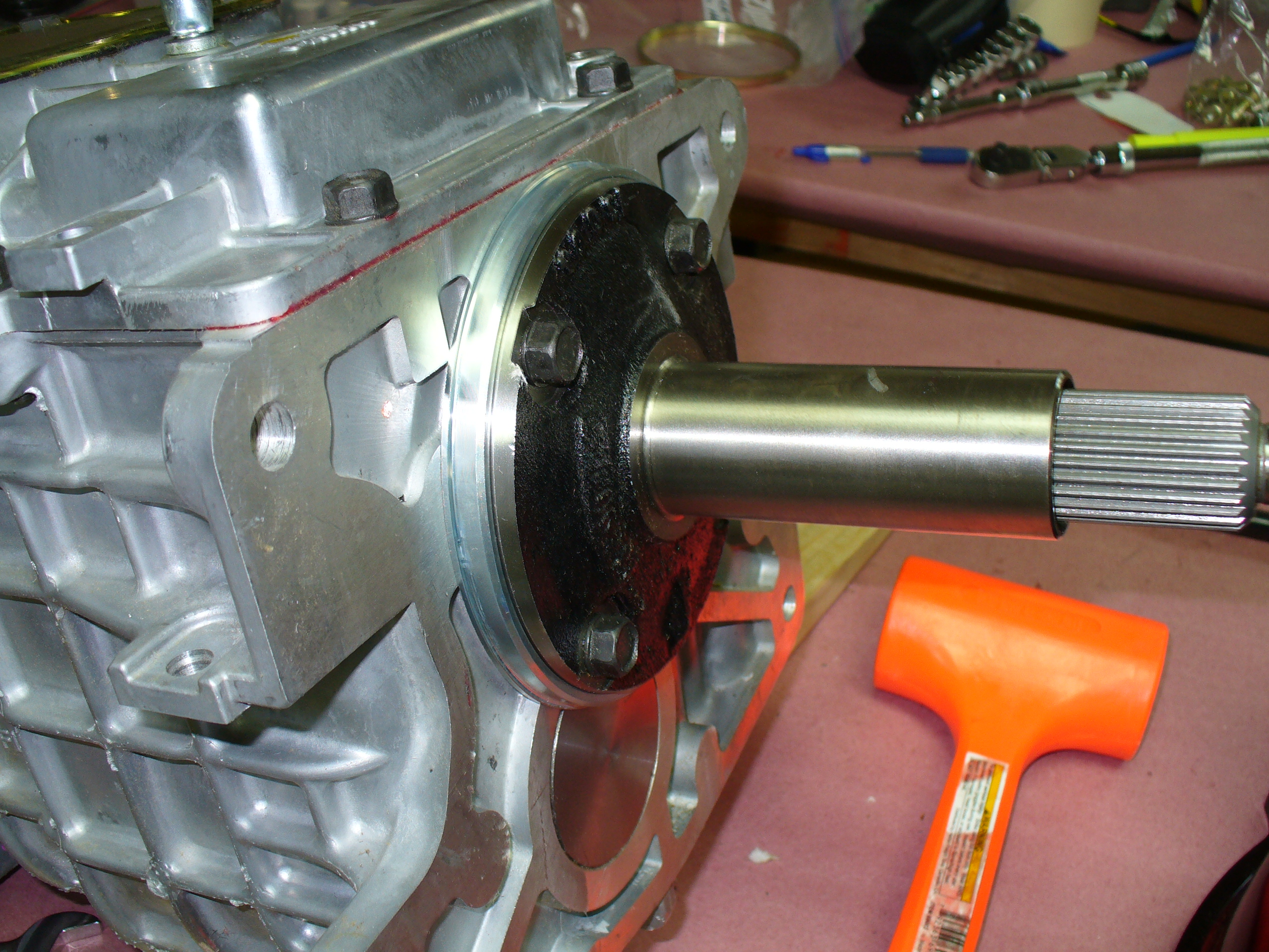
Here is the transmission, ready for the housing.


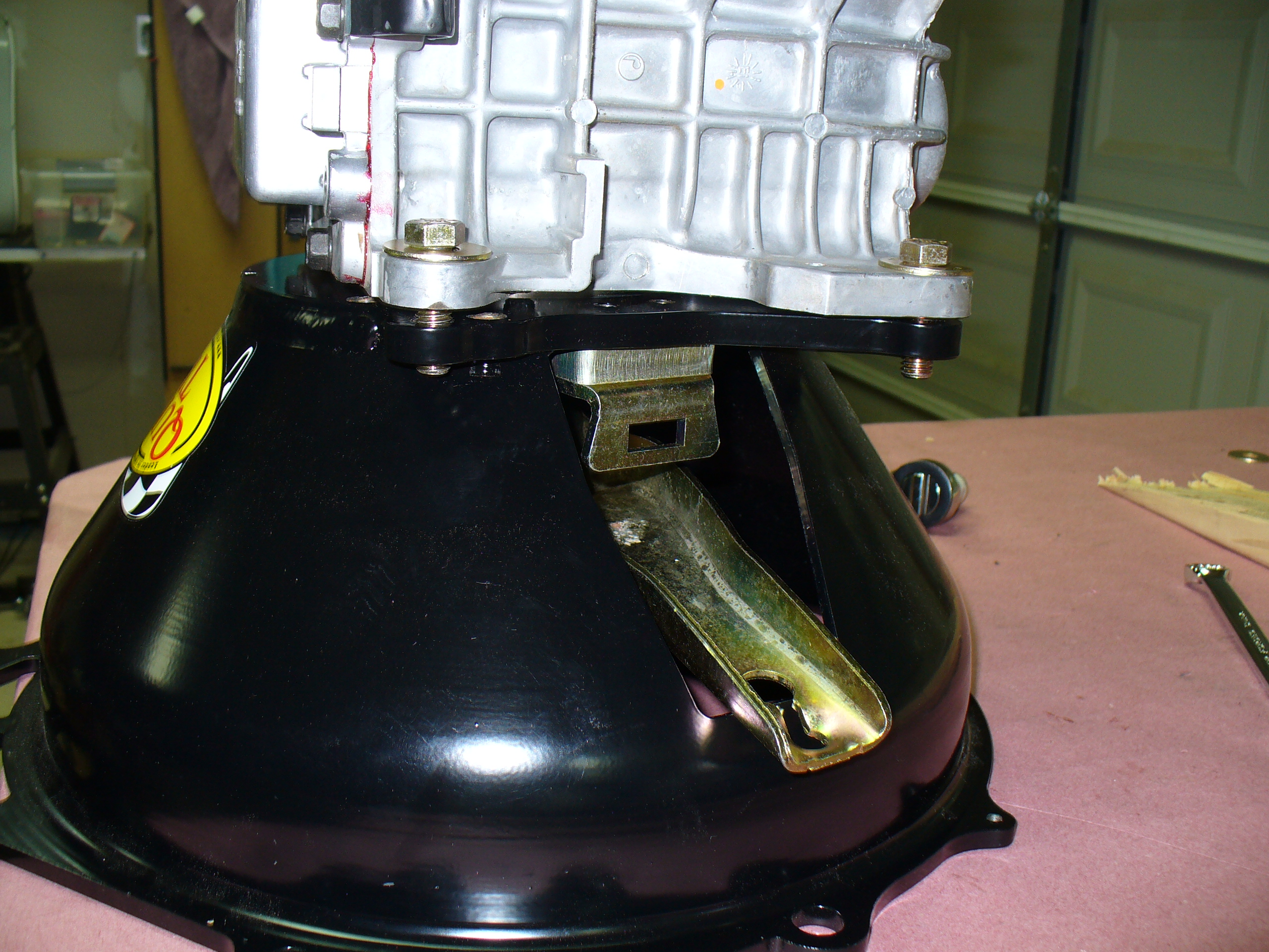
This bracket fell off the fork.

This ring went between the two parts.

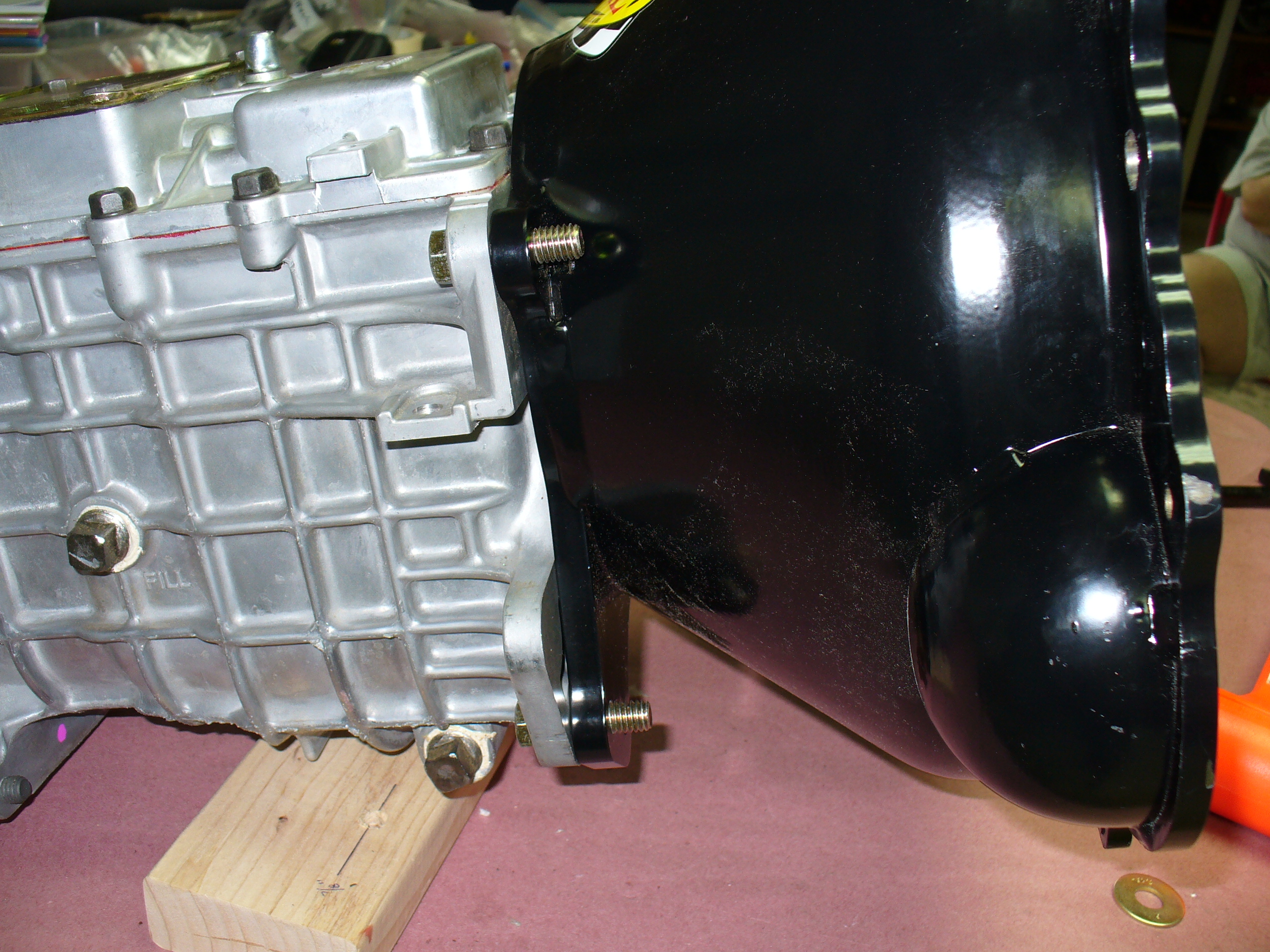


All assembled and ready to go.
Nice tool — thanks Mom and Dad for the gift!


I did not use this bracket.

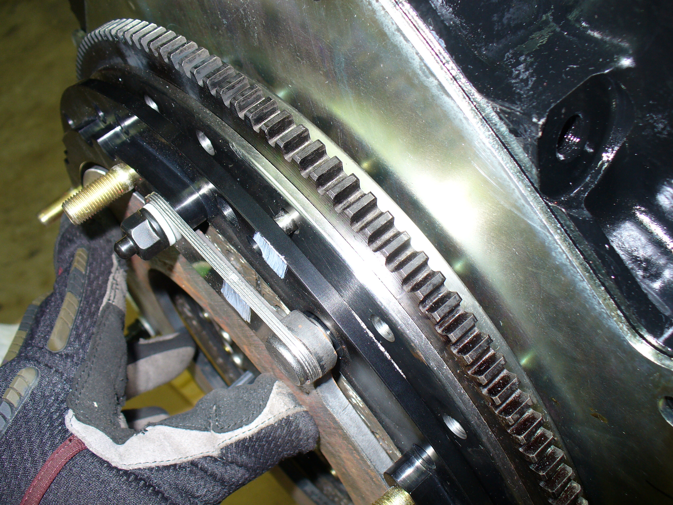
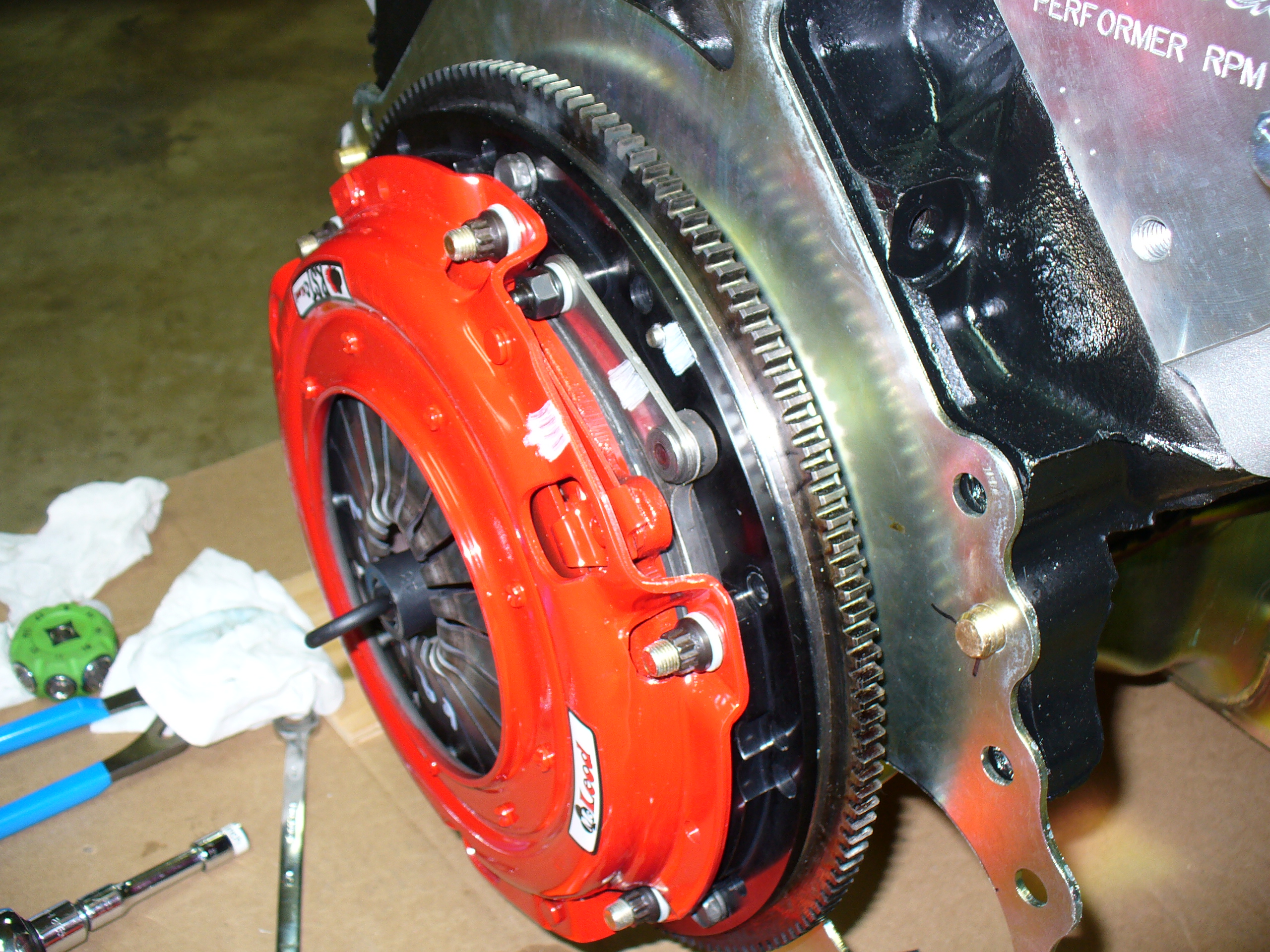
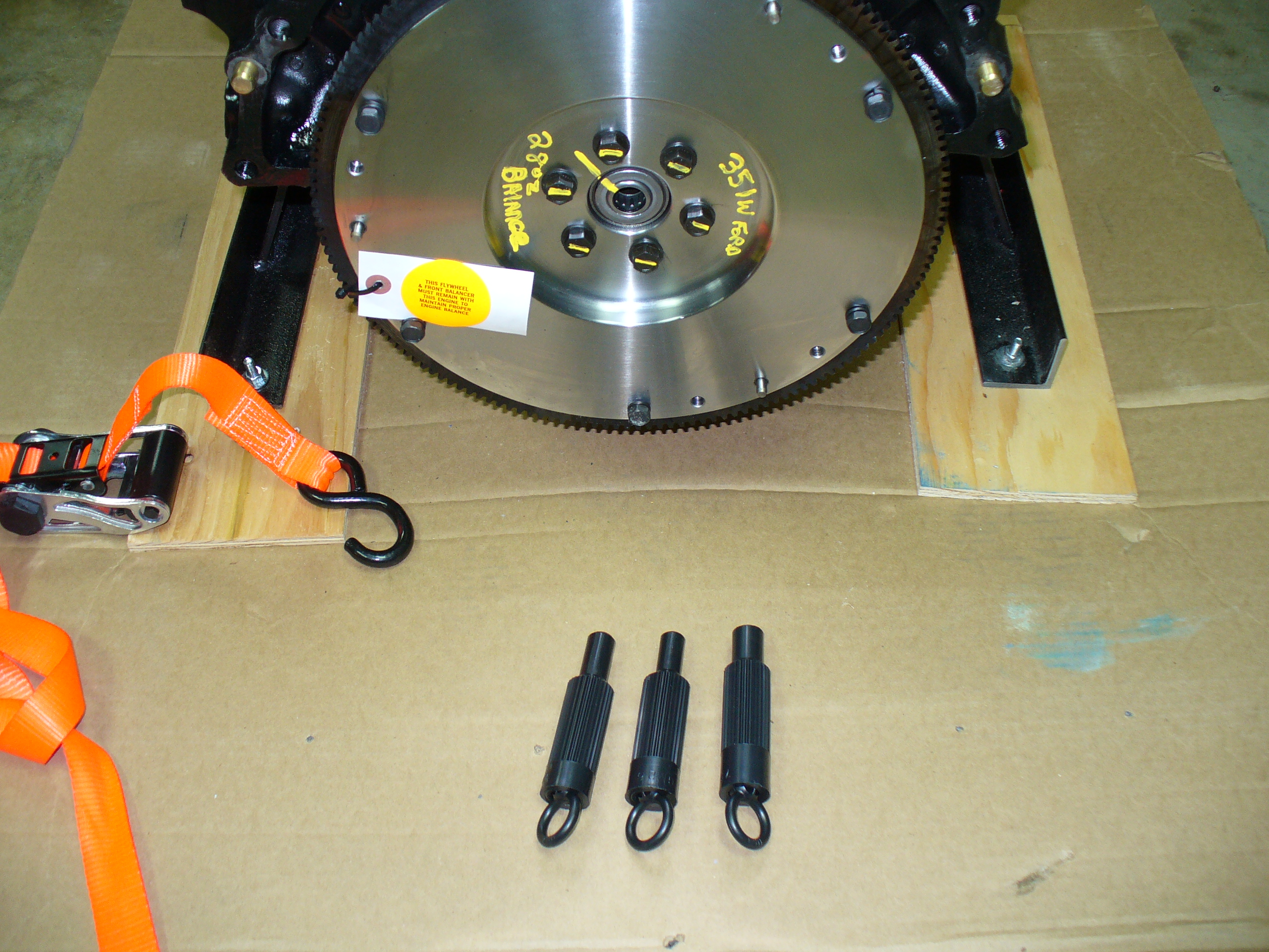
This week I was able to get the clutch installed onto the flywheel.
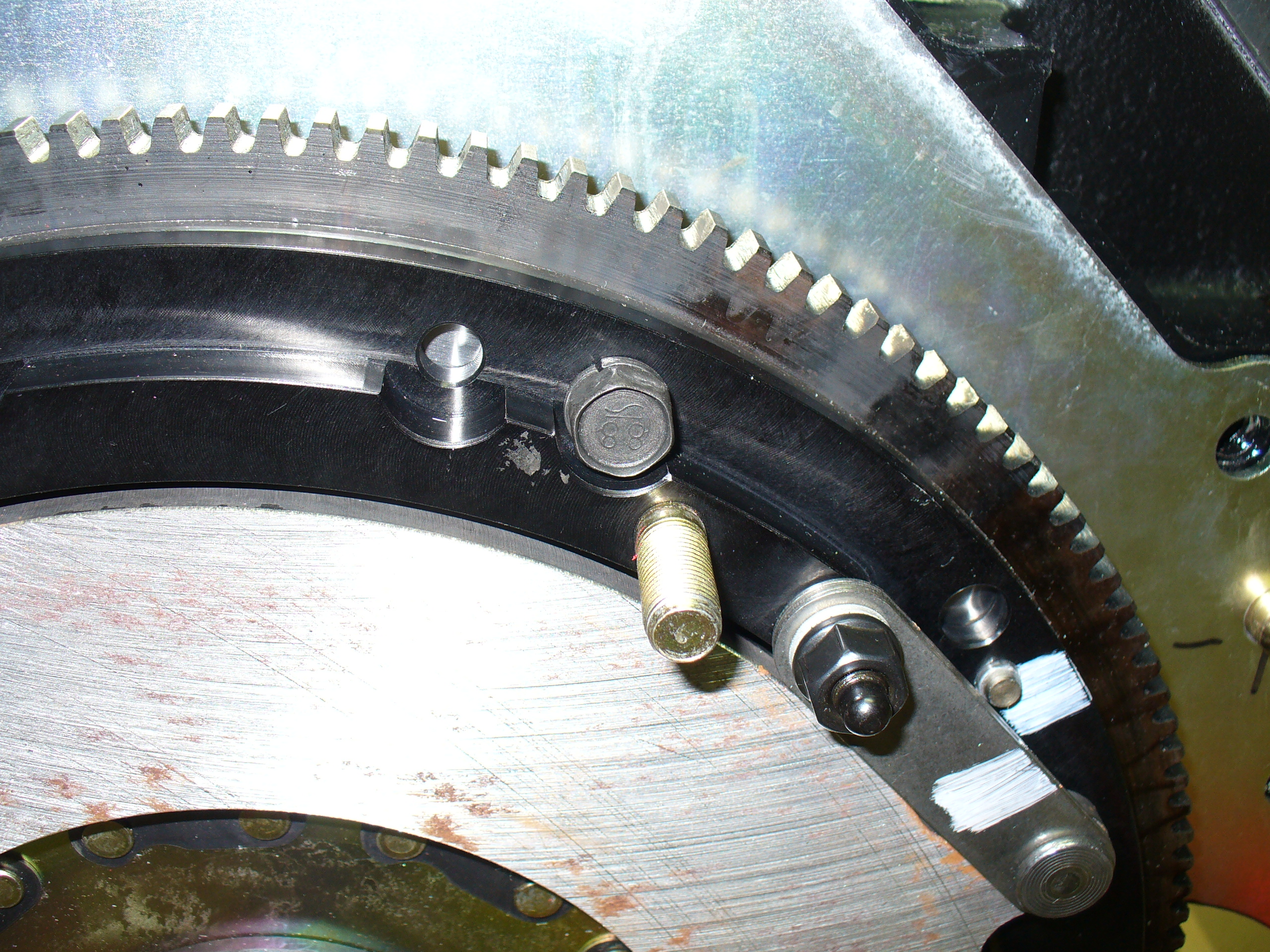
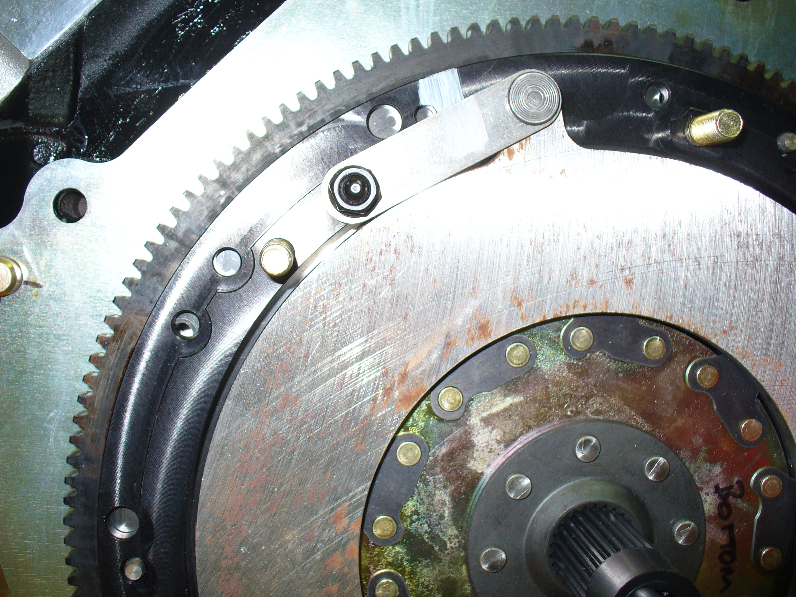
The guys at McLeod Clutches said one of the three dowels on the flywheel goes into a pilot hole under the mark on the black front ring. However, the hole wasn’t big enough to fit the dowel.
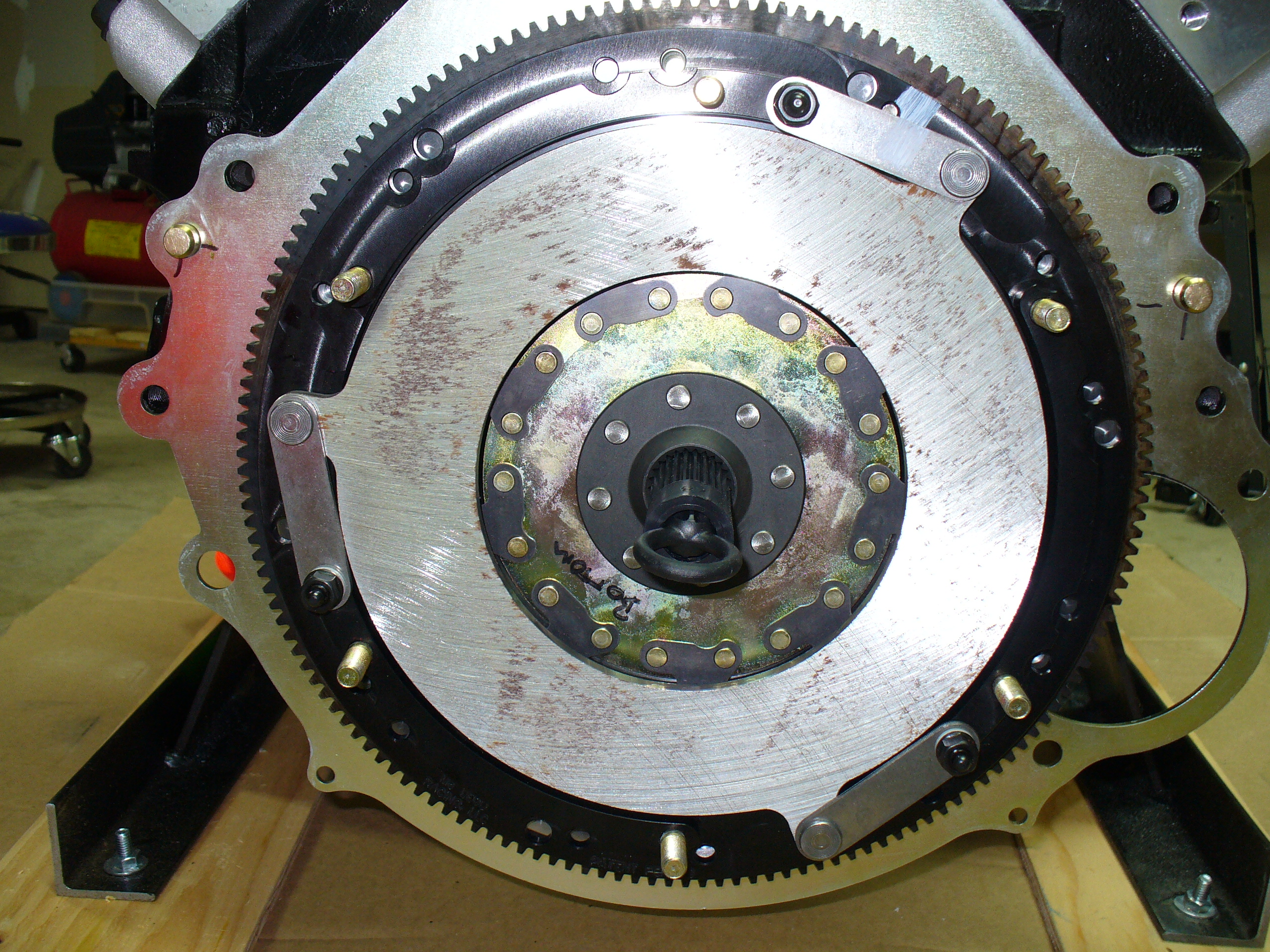
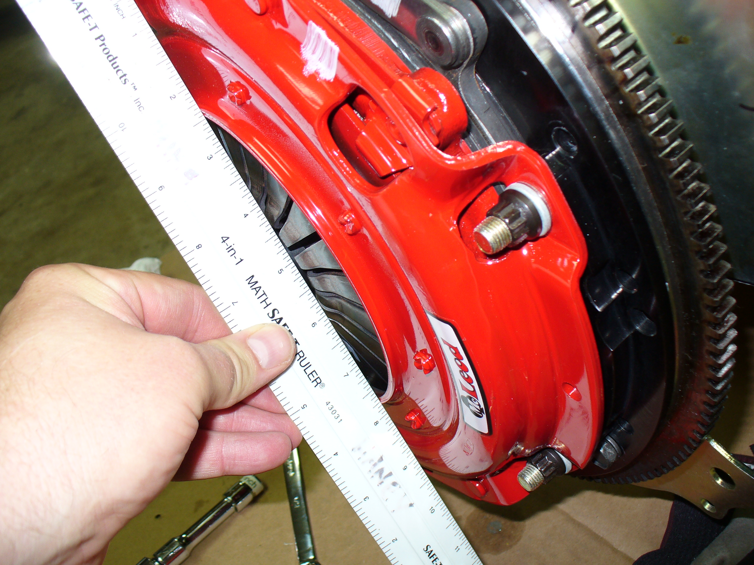
Note the gap between flywheel and clutch.
McLeod’s recommendation: just “beat it on” to the flywheel. I don’t think so!
My fix: take a round file and enlarge the hole slightly for the dowel.
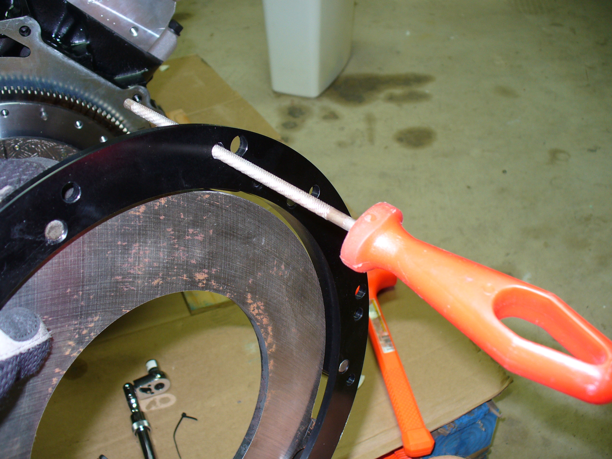

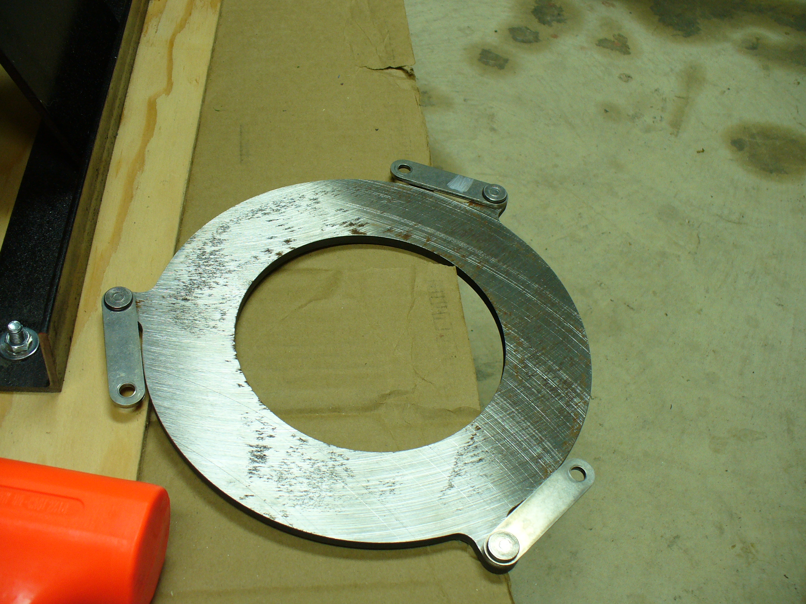
I had to remove this middle ring in order to effectively file out the hole.

Finally: all fit onto the dowels. It’s a snug fit, but it works.


I reapplied this middle ring. The front clutch plate still turns, so that’s good.

Next major design flaw: the flanges around the McLeod clutch ring are too close to the hole to allow for a socket to fully engage the bolt.
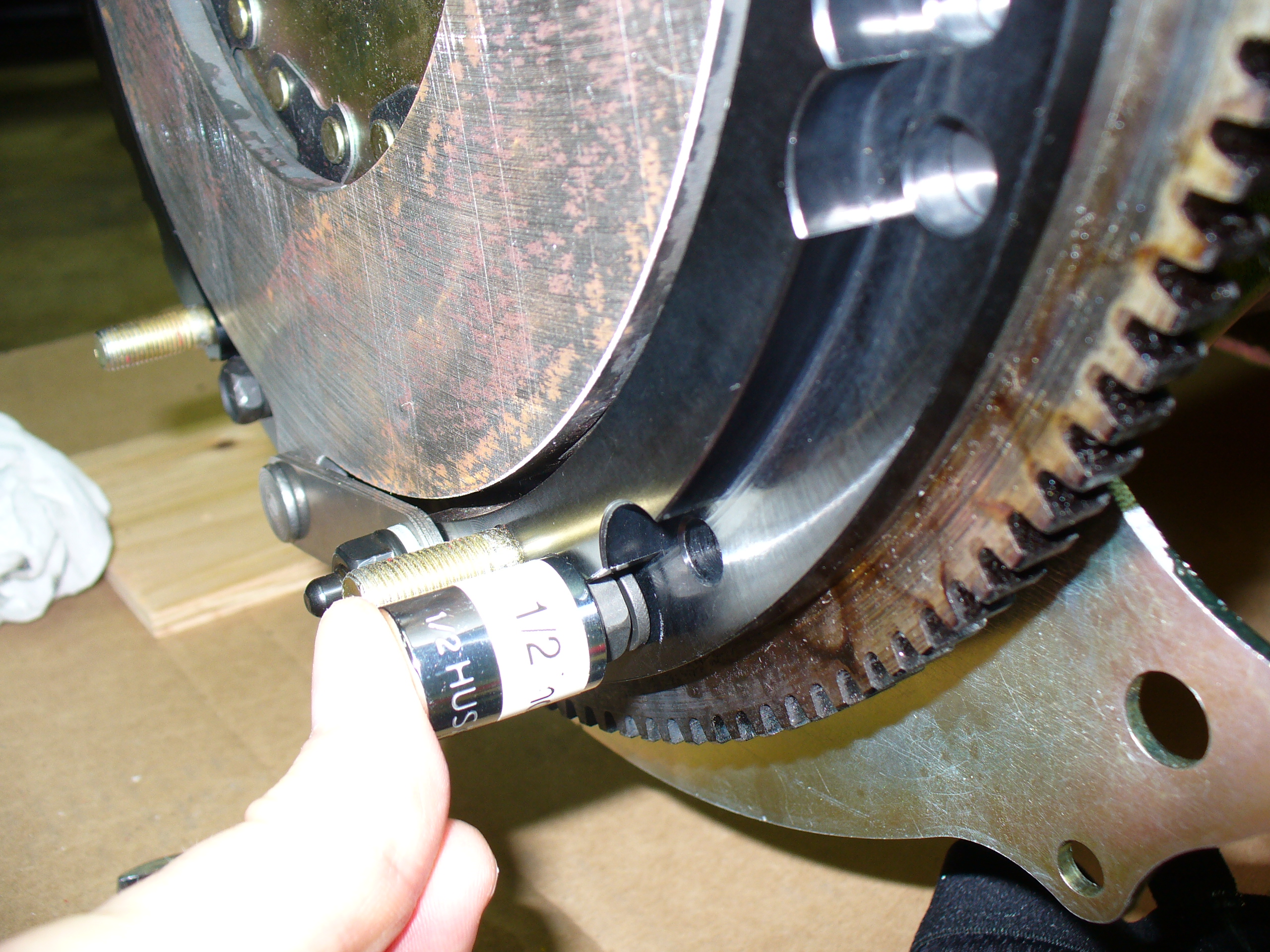
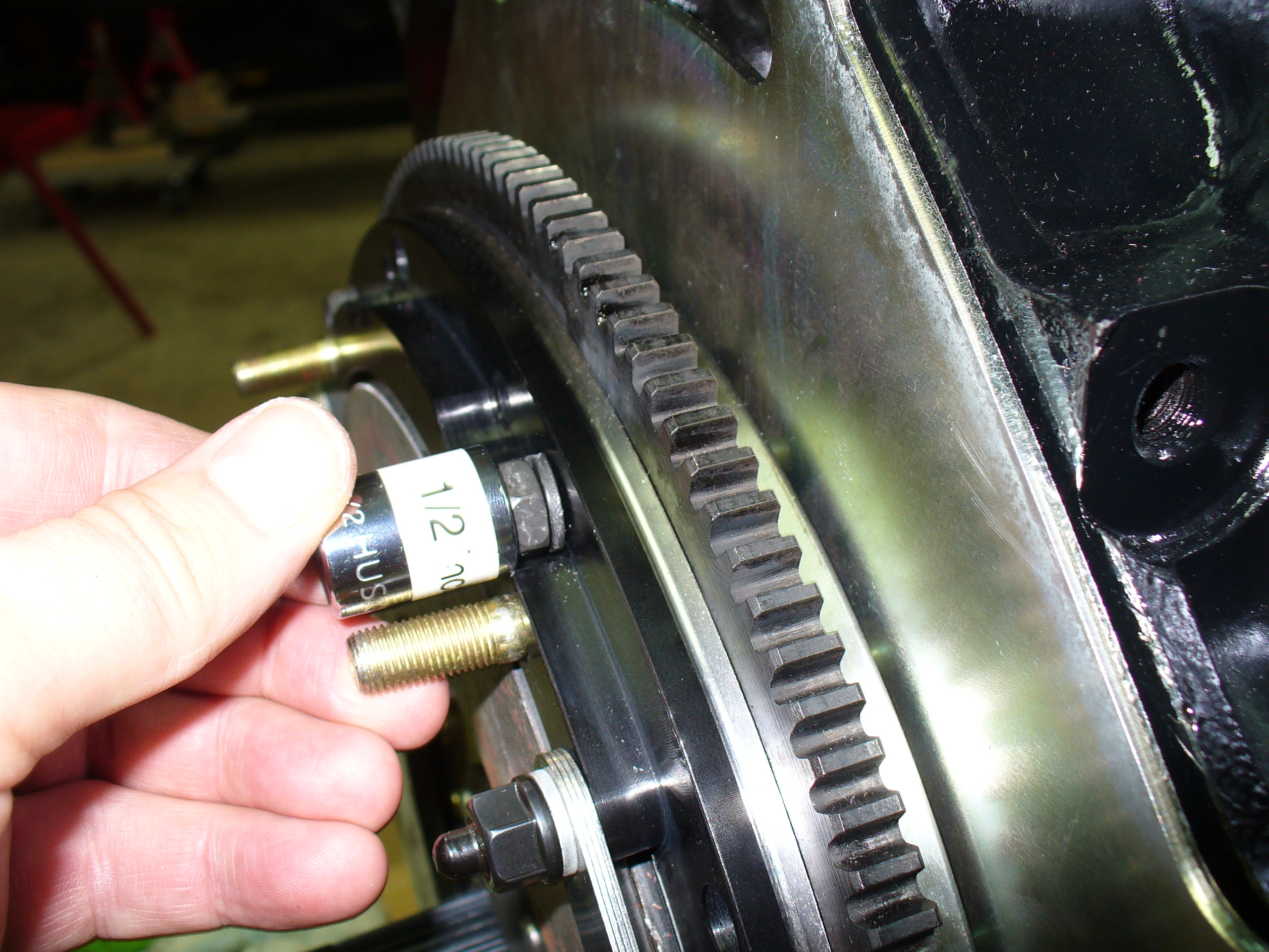
I did the best I could with wrenches and sweat.
Next, the second clutch plate goes on…

…and now the final piece of the clutch.

I used the manufacturer’s torque specs to install this part without difficulty. The little “fingers” inside the middle of the red part now are compressed down below the level of the end ring, as per the instructions.
This weekend I worked on getting ready to mate up my engine, clutch assembly, bell housing, and transmission to work as a single integrated unit. At that point, I will be able to put the entire assembly into the chassis at once.
First: a call with Bobby at Lone Star. The key order of the process is as follows:
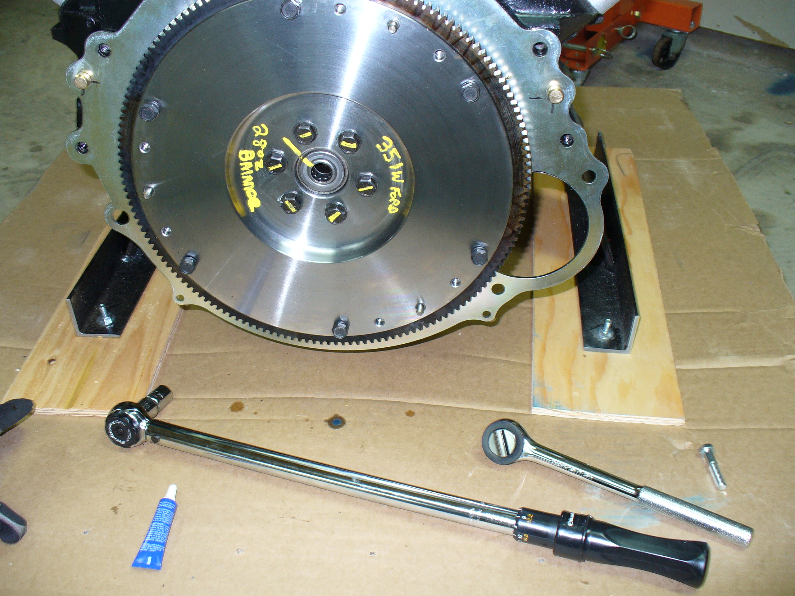
1 – Remove flywheel
2 – Install engine block plate on back of block (it came with the bell housing)
3 – Reinstall flywheel, using loctite and torquing to 60 ft-lbs
4 – Take clutch apart, then: put first clutch plate onto flywheel (holding with alignment tool), install adapter ring, line up second clutch plate using alignment tool, install pressure plate, then remove alignment tool.
5 – Attach bell housing and clutch fork to transmission
6 – Put the transmission in gear
7 – Mate up the trans to the engine, rotating the trans slightly to align the splines.
+++
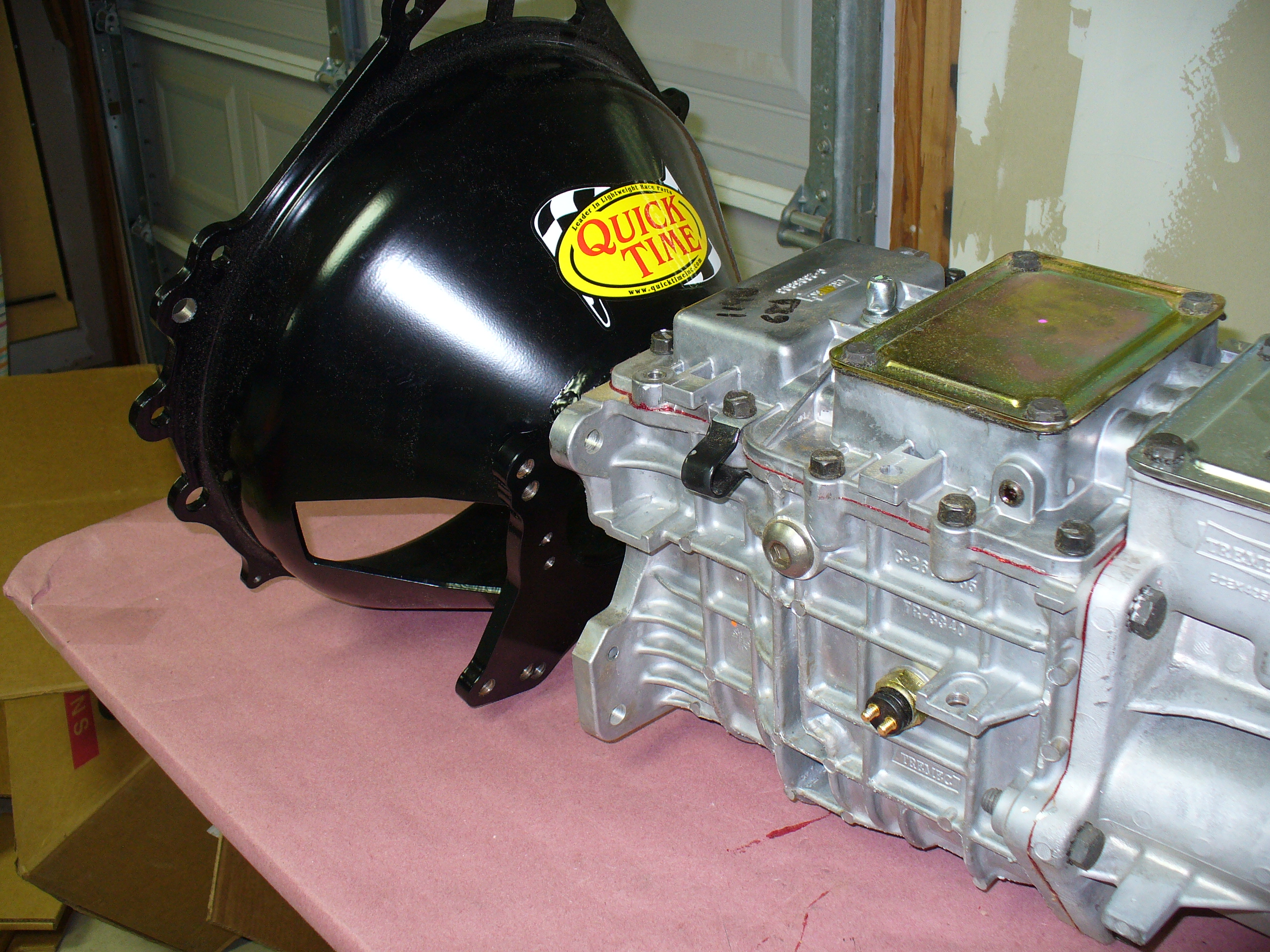
Here are two of the key components: the clutch and bell housing:


Note the flat washer goes in first, then the lock washer, then the nut.

The unit comes with all this, including three different clutch alignment tools.
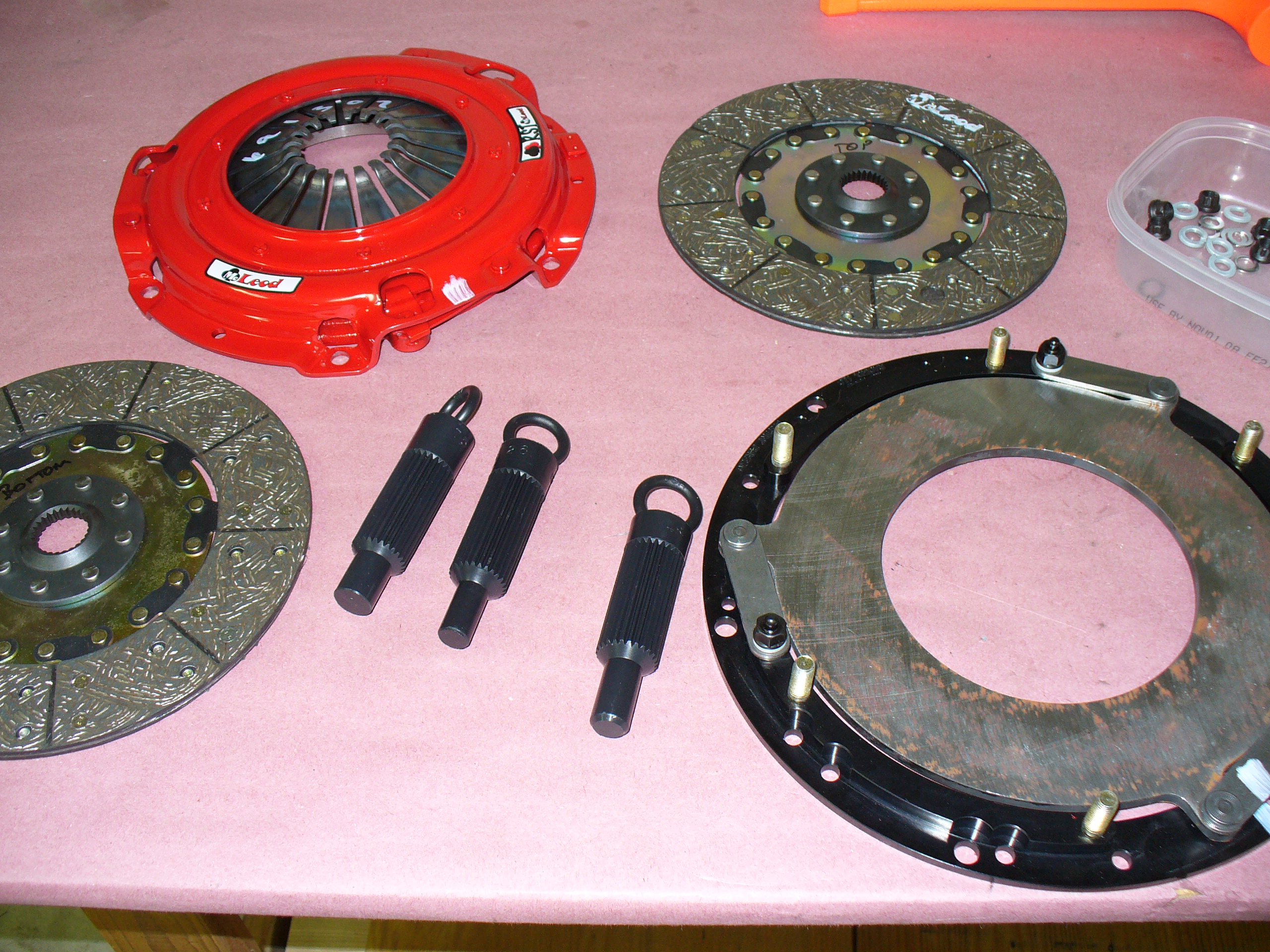
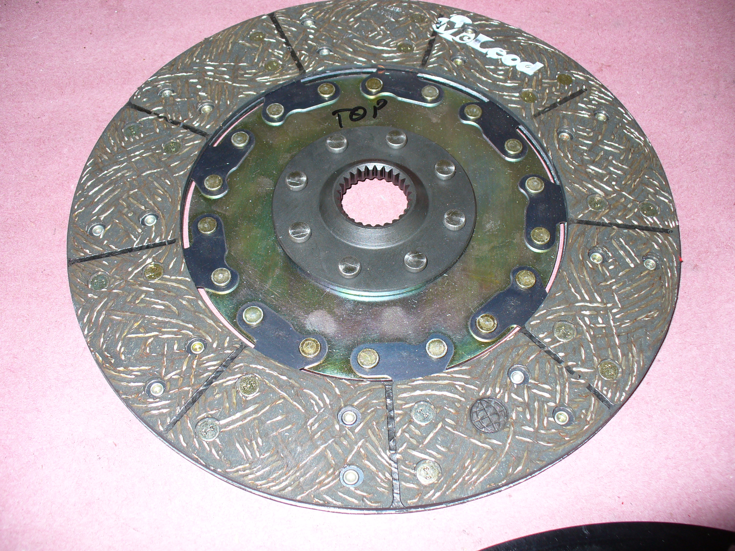
The “bottom” clutch plate, which is closer to the flywheel:

…and the top plate, closer to the transmission.
Which tool to use? The kit came with three alignment tools; only one of them fits in the pilot bushing, which is in the center of the flywheel.

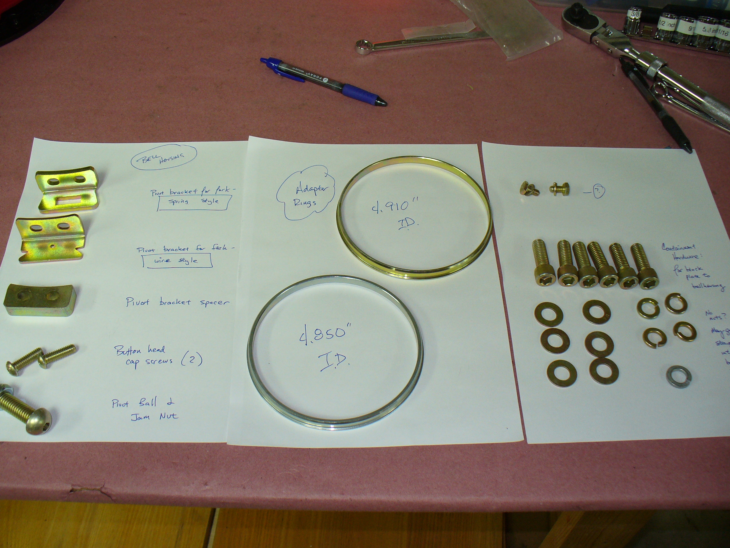
Here is the bellhousing kit, the main two pieces plus the various hardware:


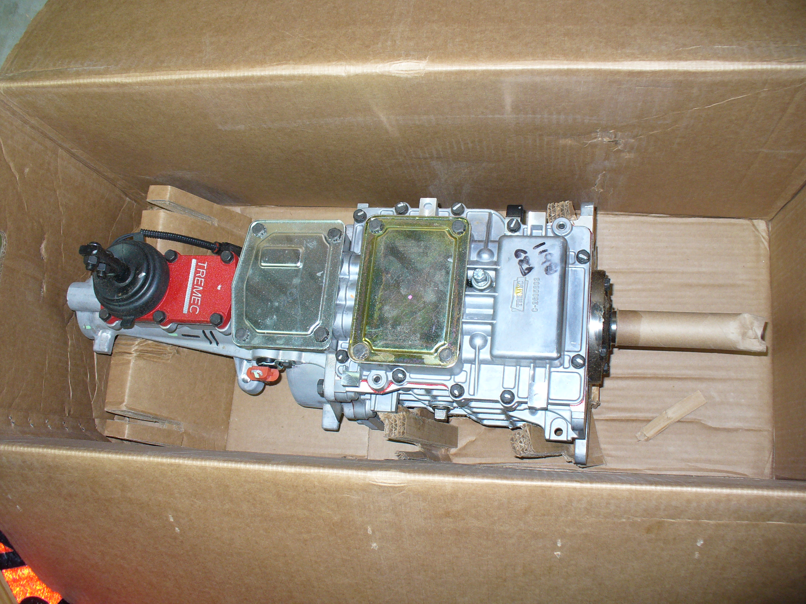
Here is the transmission:


Confirming the spline pattern is the same:

…and that the end of the unit will fit neatly into the pilot bushing:


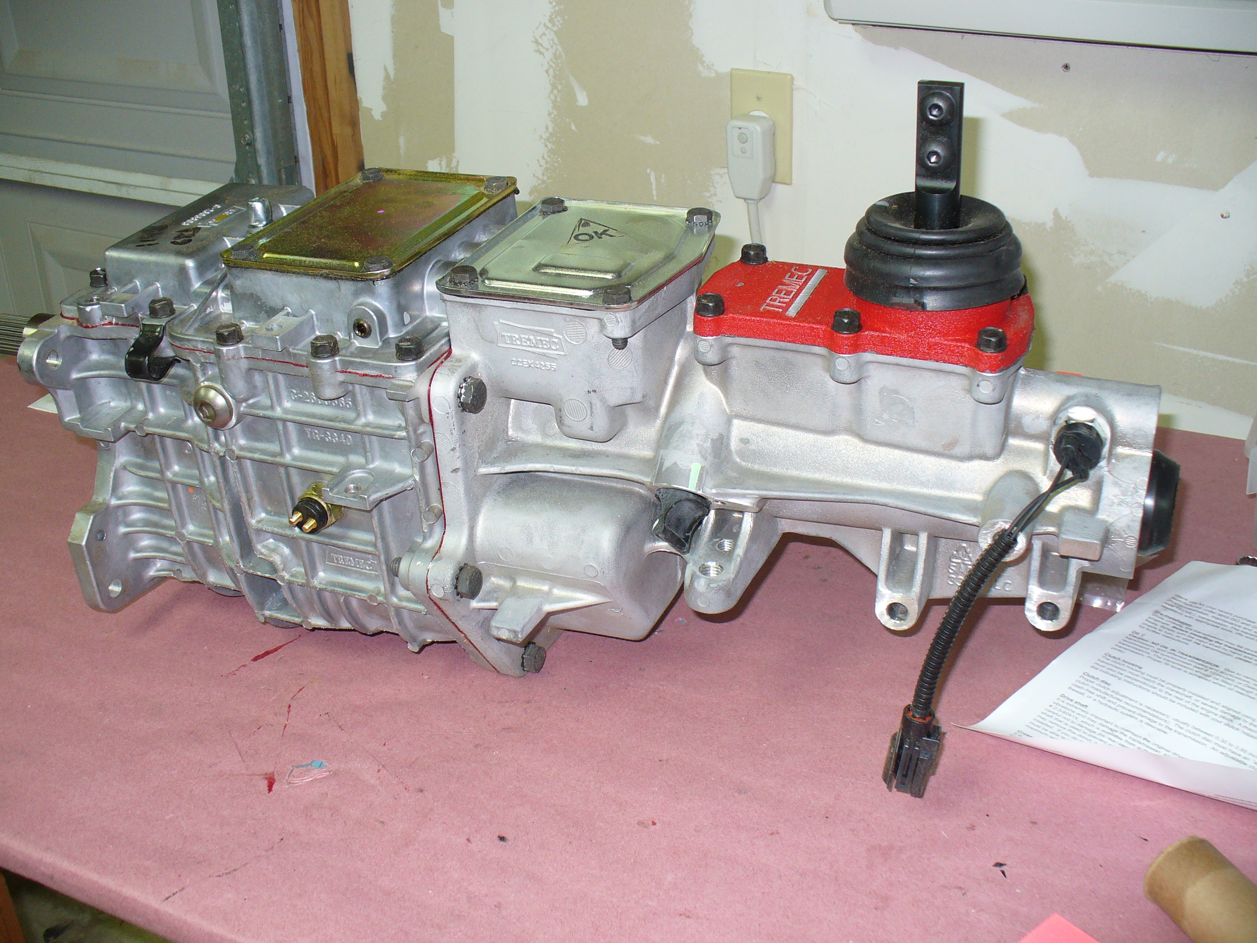
More detailed photos of the transmission:


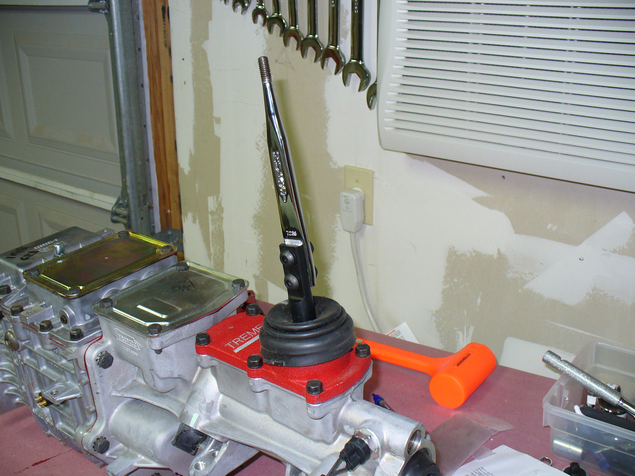
I needed to attach the shifter to get enough leverage to actually shift the transmission. I put it into 3rd gear to complete the installation.

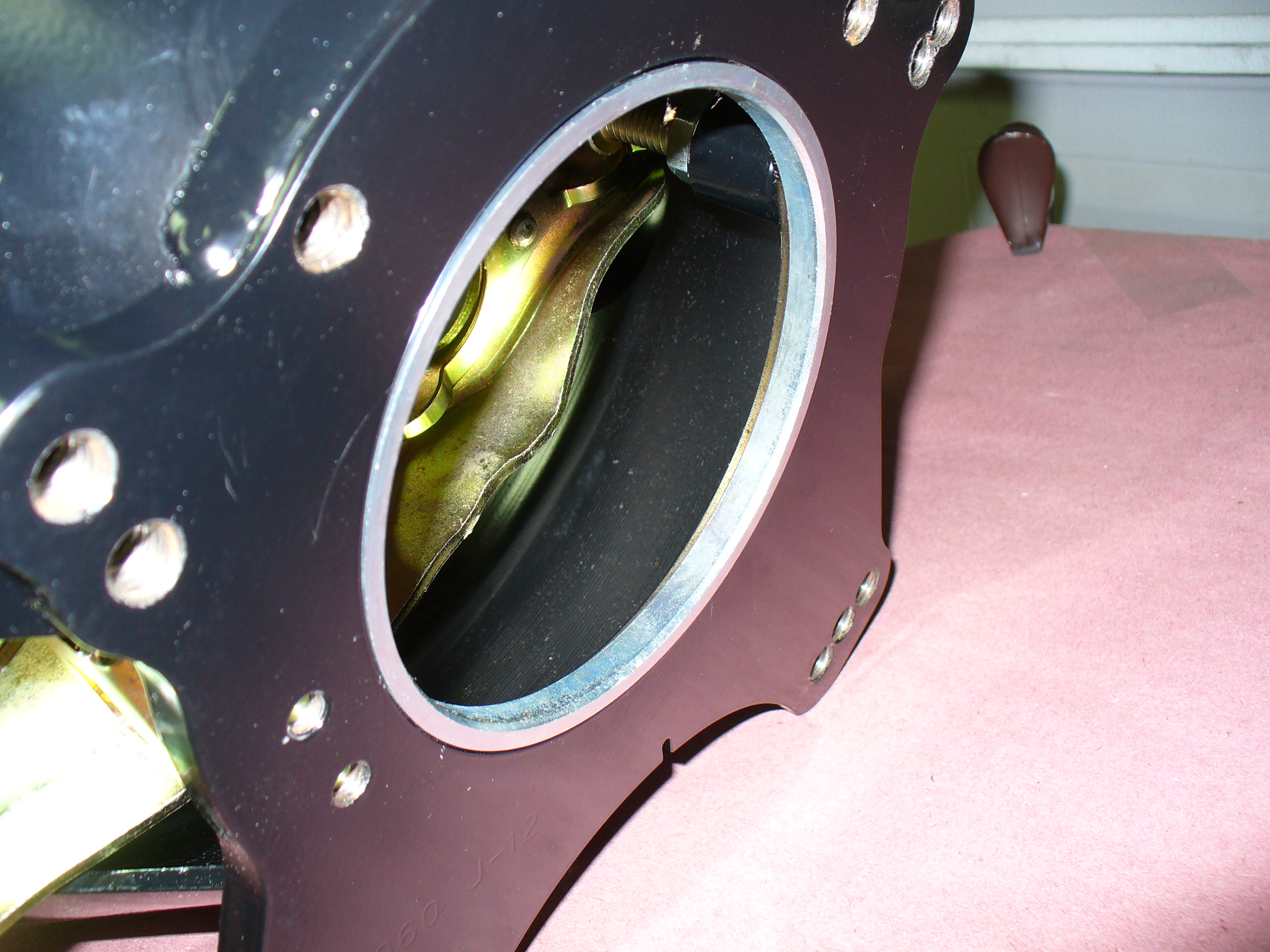
I googled installing the clutch and bell housing, and I learned a lot. Specifically, it is common for the Quick Time bell housing to need some work — specifically, opening up the holes for the dowel pins as well as making the opening for the starter a bit larger.

This is after doing a bit of grinding on the hole to enlarge it a bit. It wouldn’t fit this dowel otherwise. Glad I researched that earlier: it would be frustrating to get all this out and up against the block and find it didn’t work.

Removing the bolts holding the flywheel. A bit of a white knuckle experience — I didn’t know what might come out of the back when I did this. These are metric bolts for some reason.
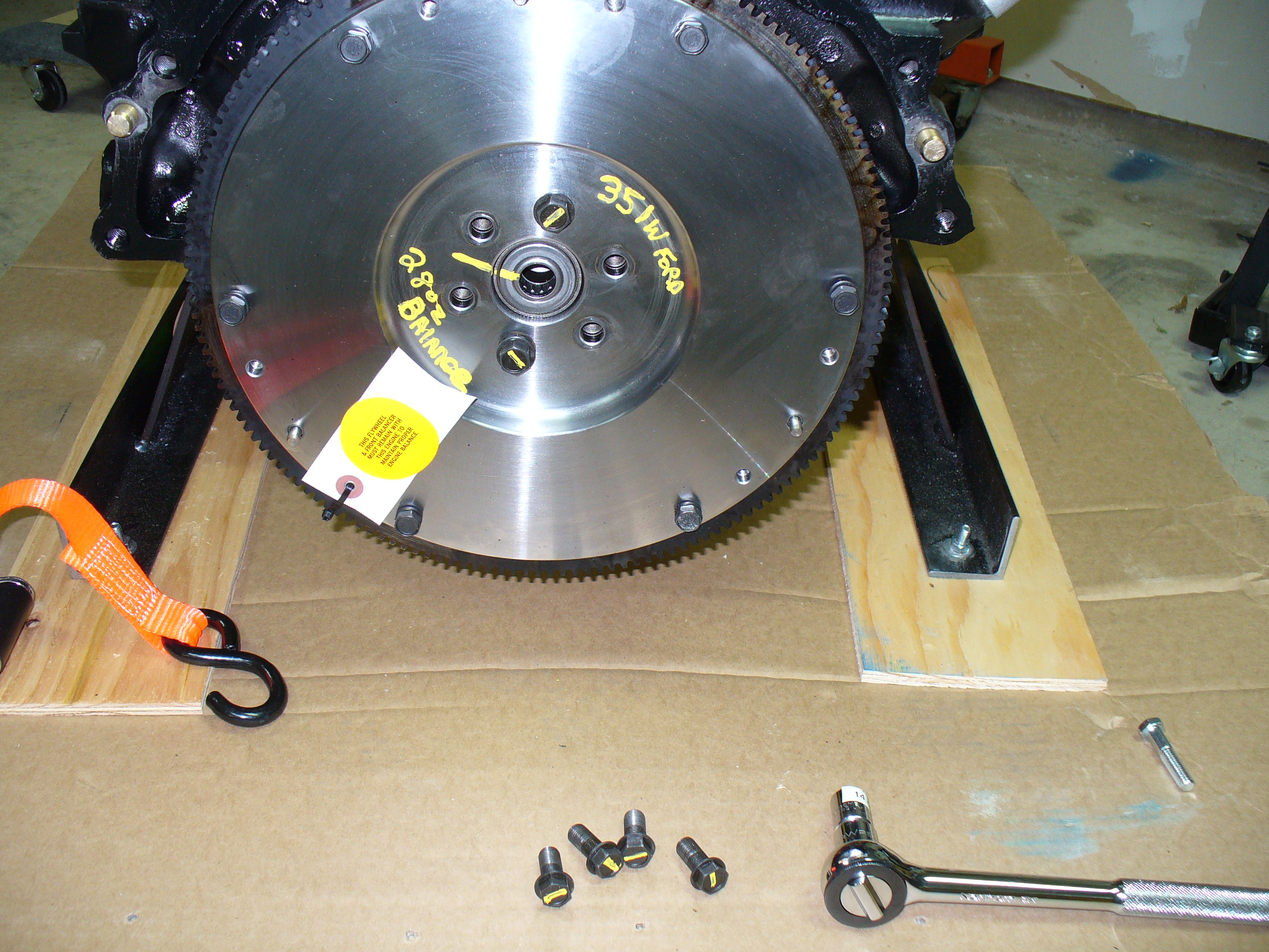
The flywheel removed. I am pleased that the bushing stayed in, and that the seal looks good. This wasn’t off the engine long…

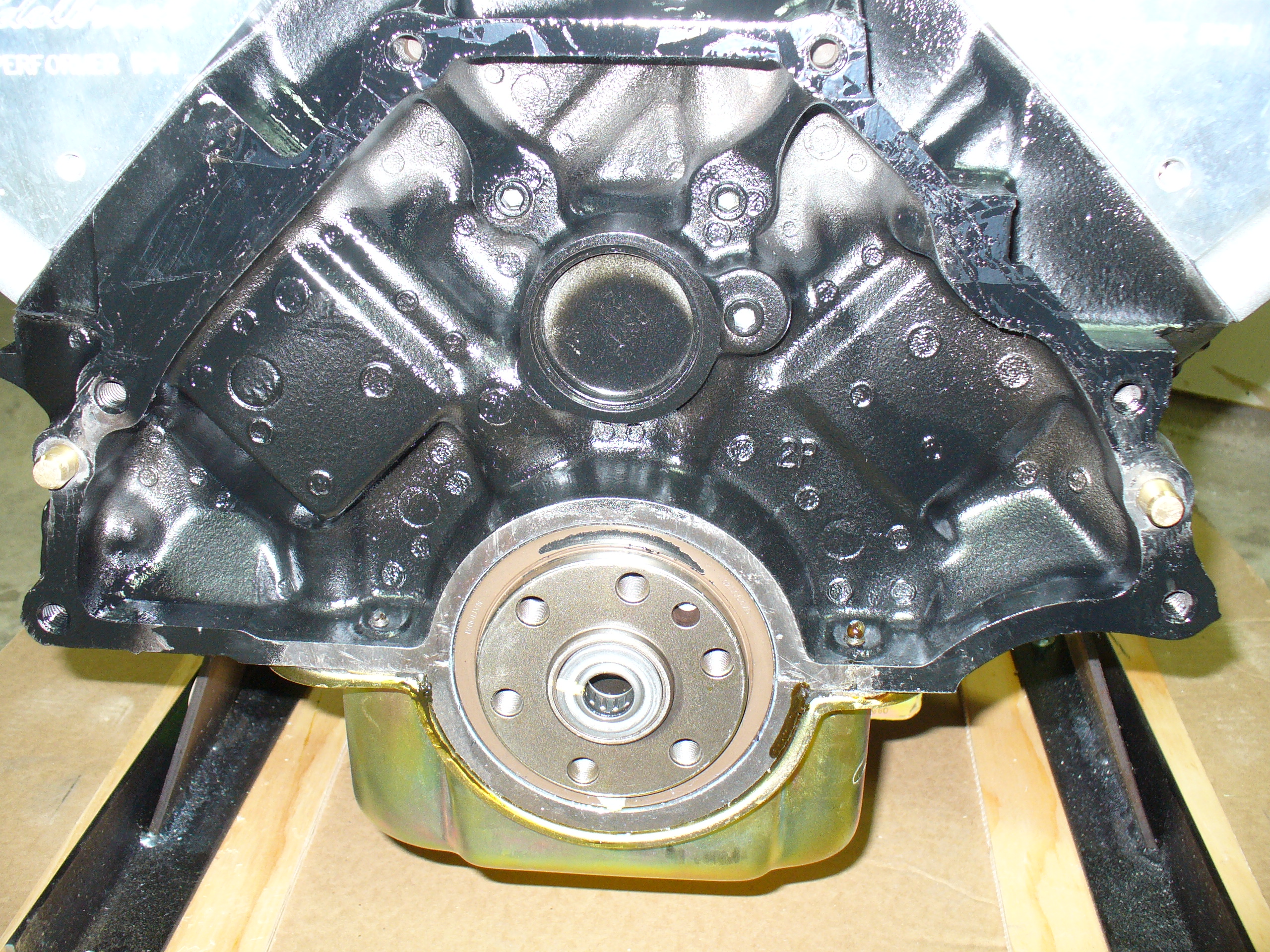
On with the cover. The dowels just fit snugly, after using my grinding wheel on my air compressor. I also enlarged the starter hole slightly as indicated from several sources, including Engine Factory.

Used this stuff when I reinstalled the bolts for the flywheel:
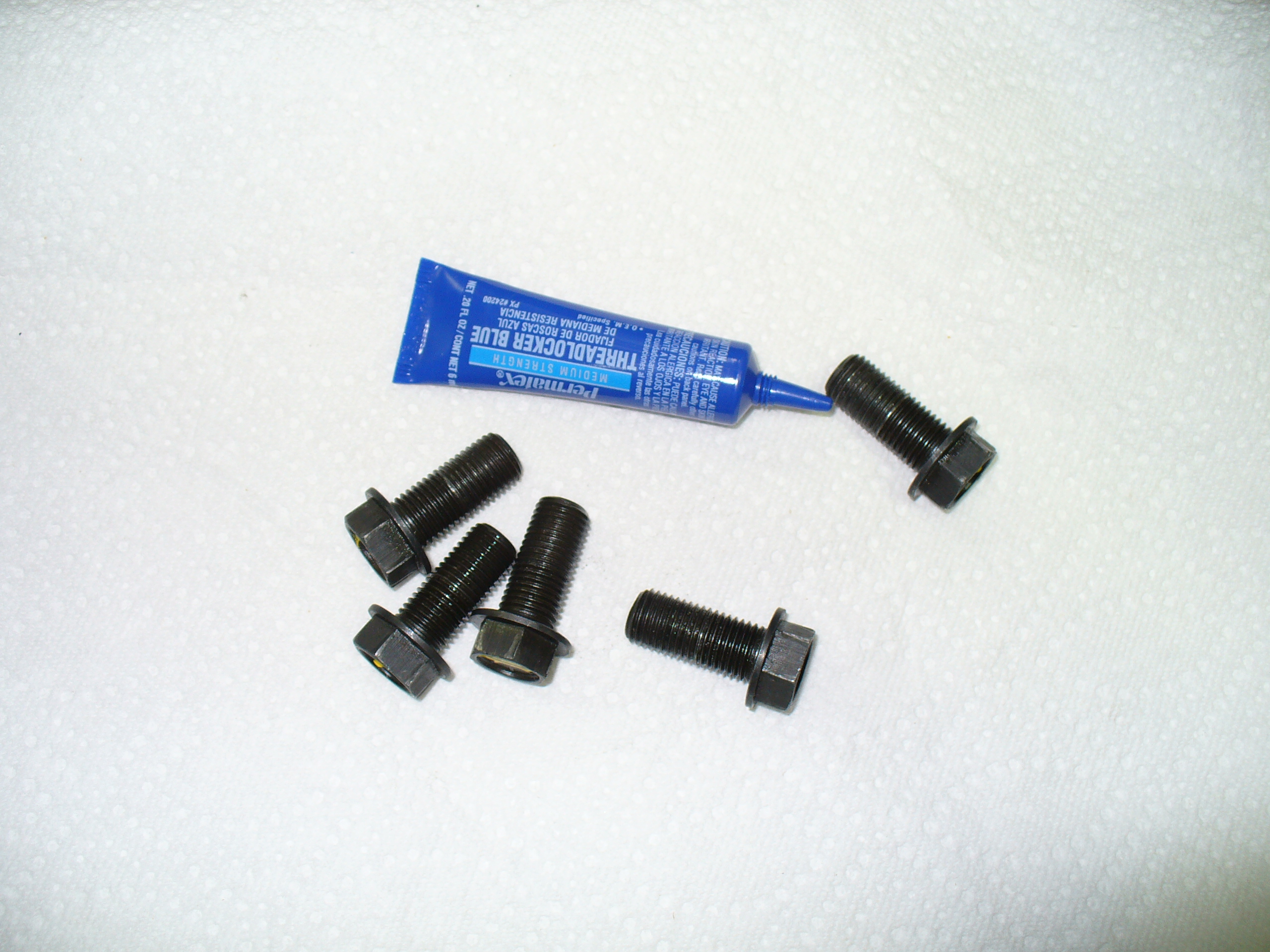
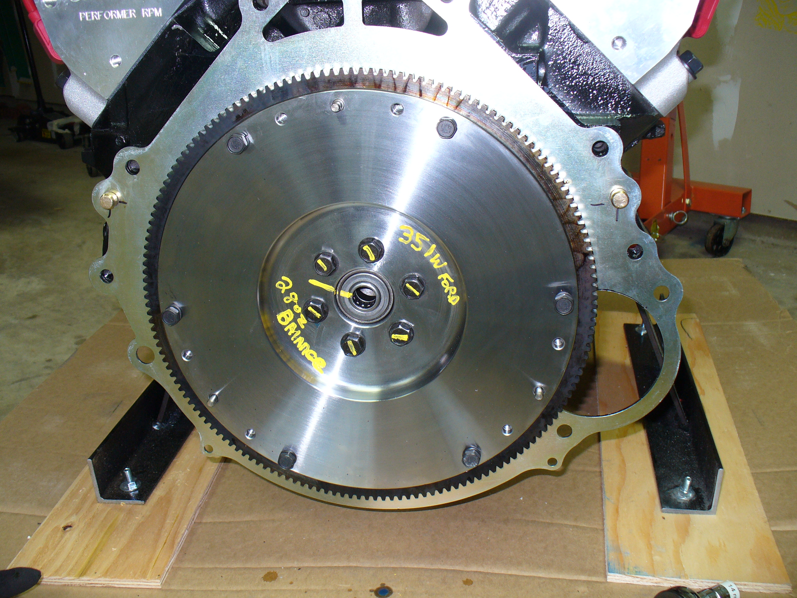
All torqued up…
The alignment tool is in…


…and now the first of two plates.

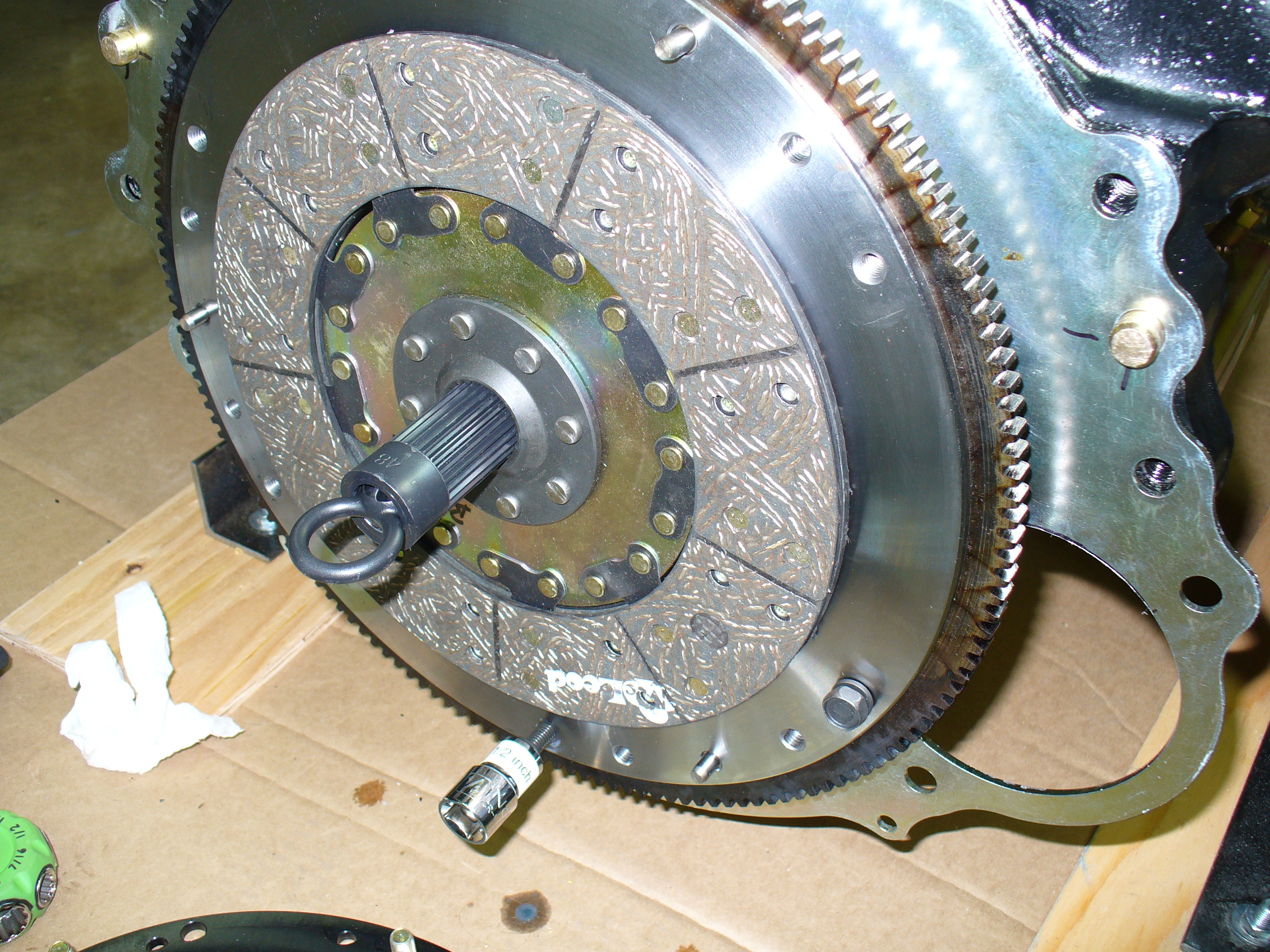
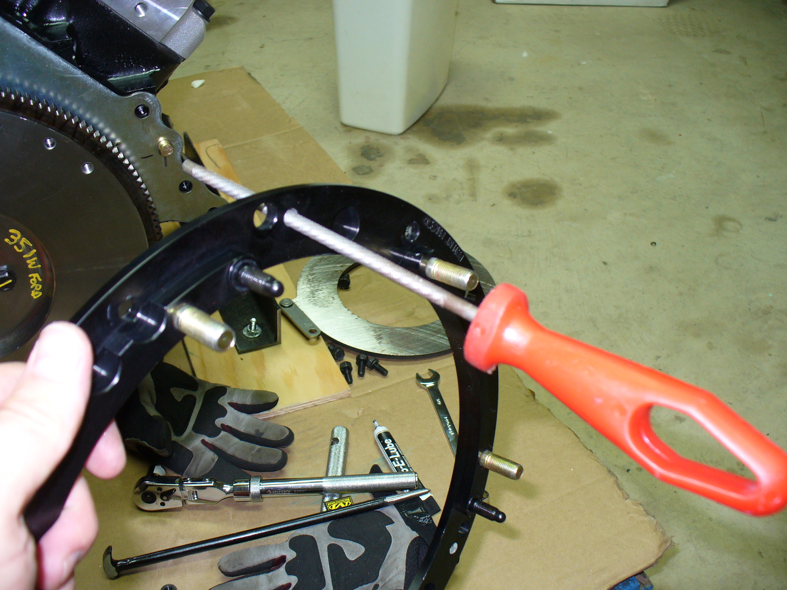
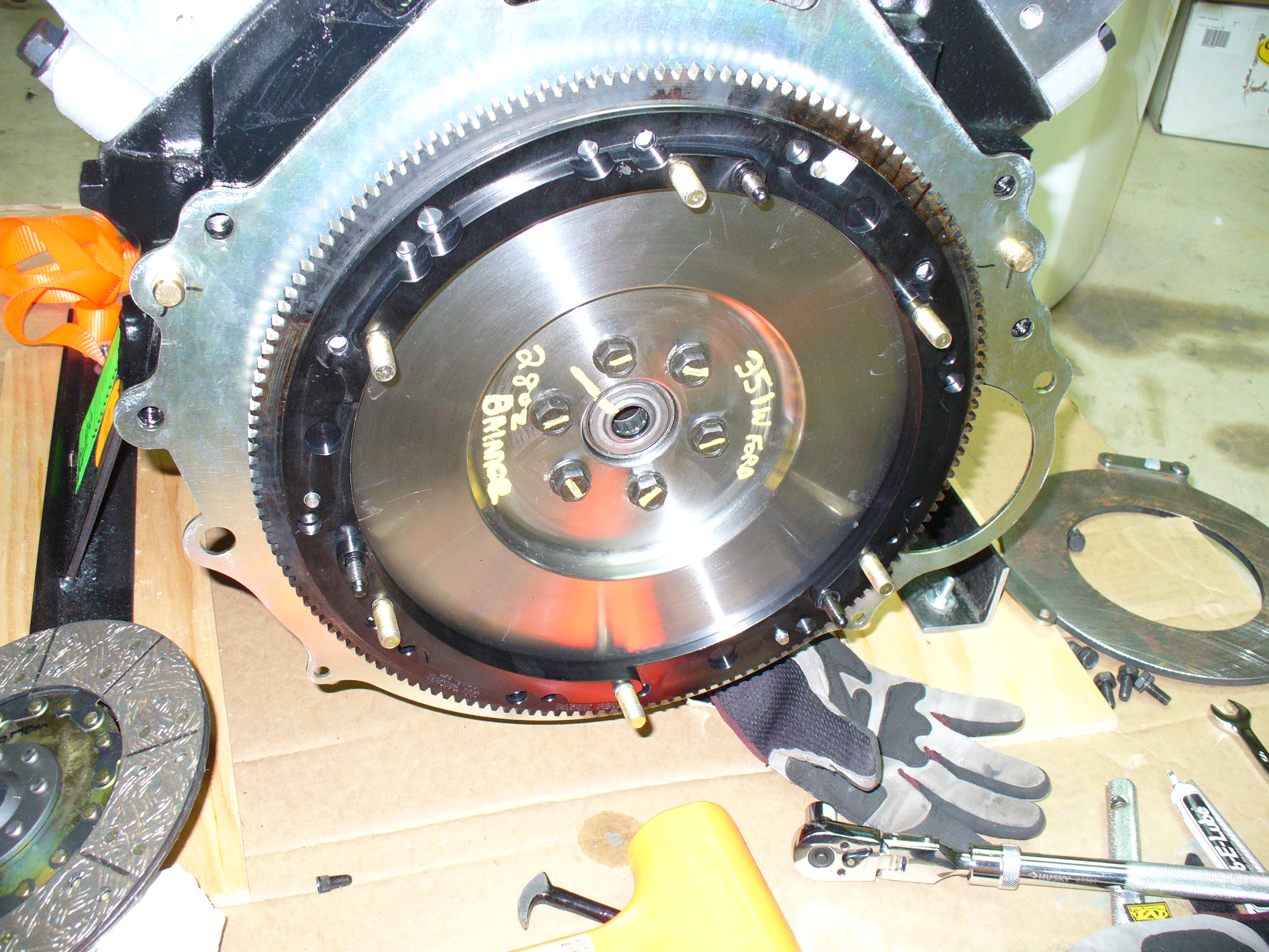
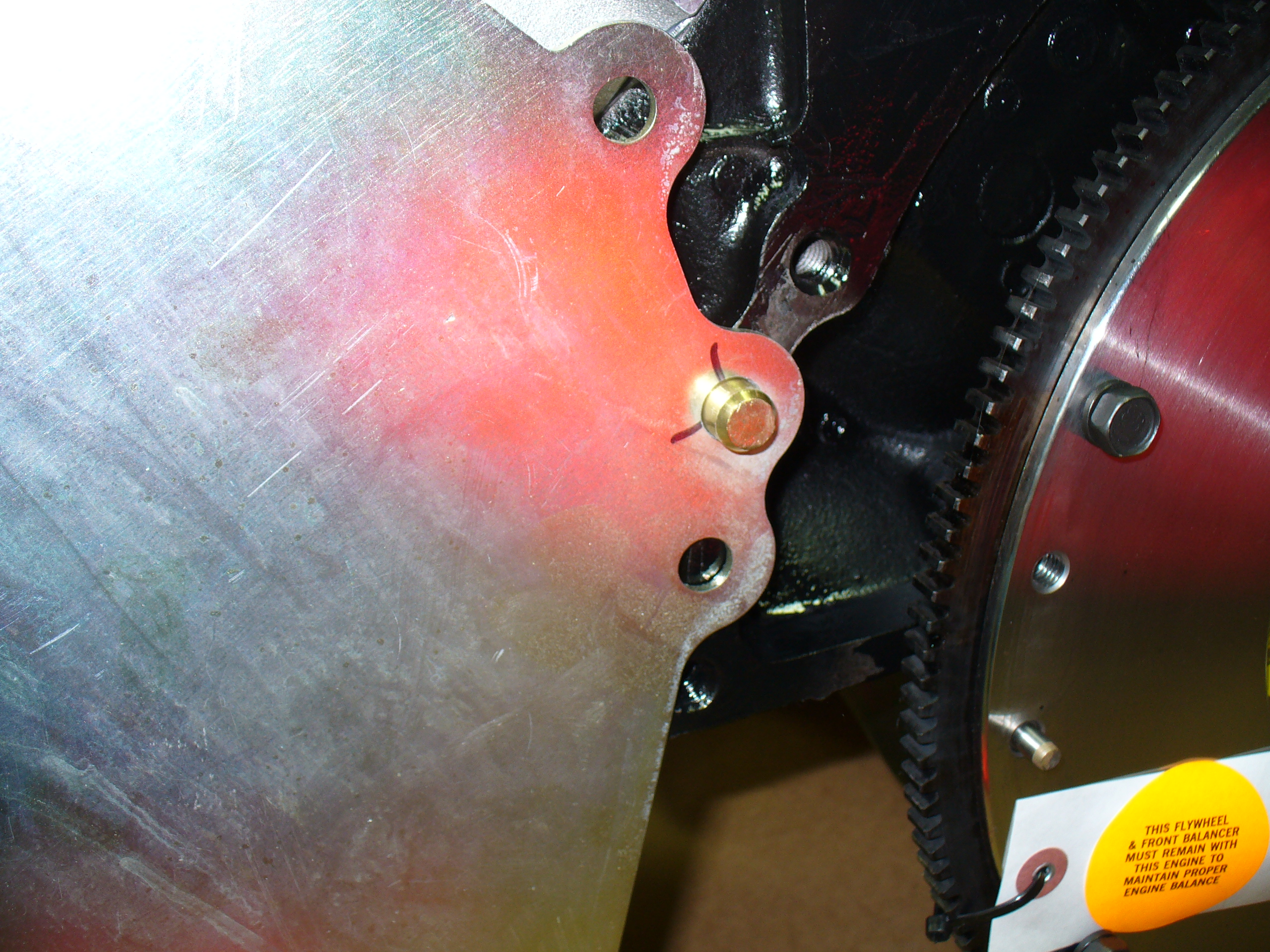
First major roadblock thus far: this next piece is the adapter ring. It is supposed to fit on the three dowels on the flywheel, then you should be able to attach it to the flywheel with the six 1/2-inch bolts.

However, I went around the flywheel using every possible combination, and each time I was able to find a position that the adapter plate aligned with the dowels, I couldn’t see the bolt holes in the flywheel through the adapter plate holes.
This made me suspicious that I may have the wrong part for my 351W small block Ford. I called Joe at Dederich Motorsports on a Sunday, and he agreed to research this and get back to me.

Chris at the Engine Factory provided the following specs regarding my flywheel: it is Ford Racing part number M6375A302B. It has 157 teeth and has a 13.25″ diameter. It accepts a 10.5″ clutch.
So: stay tuned…
Went to Harbor Freight and bought a new set of larger combination wrenches today and threw this rack together to hold them all:

Note I had a couple of these wrenches in a few sizes.
I used the larger ones to tighten the nuts and bolts in the rear differential. I also used my impact wrench — it’s a great day when you can use that tool!
